[wiki:FsTutorial top] | [wiki:FsTutorial/Overview previous] | [wiki:FsTutorial/GroupAnalysis next]
FreeSurfer Tutorial: Morphometry and Reconstruction (90 minutes of exercises)
1.0 The recon-all command and alternatives
The ["recon-all"] script is used to process raw scan data, segment the white matter, generate surfaces from the segmented data, and output spherical or flattened representations of the surfaces. Recon-all may be used to execute all or part of the volume and surface processing pipelines. Alternatively, scripts exist to execute chunks of each processing pipeline, and individual commands may be run to execute a single processing step. FreeSurfer makes all of these approaches available, and the user may choose the one(s) which are most comfortable on a case by case basis.
[wiki:FsTutorial/Tools Tkmedit] and [wiki:FsTutorial/Tools tksurfer] are programs that are used to visually inspect the data at key points during the reconstruction process. Tkmedit provides an interface to view and edit voxels on 2D scan slices, and tksurfer is an interface to view the 3D generated surfaces. The reconstruction steps are not immune to failure, so it is necessary to inspect the output as the reconstruction proceeds. The reconstruction steps can fail for many reasons including differing anatomy between individuals and scan quality. In this section's exercises, some of the more common failure modes and ways to correct them will be shown. Both the volume and surface data processing paths in FreeSurfer will be described; for some stages, before-and-after images will illustrate the way data is modified at each step. But first, the manner in which data are prepared for processing in FreeSurfer will be described.
2.0 Volume and Surface processing: recommended workflow using recon-all
Recon-all is a script that is capable of running any single step in the anatomical processing stream, as well as running sets of steps with a single simple command-line interface. When this script is used you will also be generating many log files so that you can track your progress, troubleshoot failures and repeat exact commands if needed, these files are not created if steps are run outside the recon-all script. To reveal the flow of this processing, a more in-depth look is given below. For clarity, the pipeline is presented below in two logical chunks: the volume processing pipeline and the surface processing pipeline. Recon-all can be used to execute the entire processing pathway, using the command:
recon-all -autorecon-all -s <subjid>
If you know that your data is not prone to failures it is perfectly acceptable, and recommended, to run the entire process at once and check all output at the end, in the manner presented above. If it is your first time going through with your set of data, if your data is prone to failures, or if you want to be sure that you do not waste processing time, it is possible to break this total process into 3 smaller pieces, allowing you to check for and correction of errors at a few key points.
The logic of the workflow will become more evident as the volume and surface processing streams are described, and as the points at which troubleshooting may be required become clear. The overall workflow for manual checking of intermediate steps is listed below:
2.1 Workflow BR
recon-all -subjid <subject name> -autorecon1
- stop to check for problems with intensity normalization, talairach transformation and skull stripping
recon-all -subjid <subject name> -autorecon2
- stop to check final surfaces and make appropriate edits
- if:
the WM volume was edited: recon-all -subjid <subject name> -autorecon2-wm
control points were added: recon-all -subjid <subject name> -autorecon2-cp
the BRAIN volume was edited: recon-all -subjid <subject name> -autorecon2-pial
recon-all -subjid <subject name> -autorecon3
The individual steps in this workflow will be described in context within the volume and surface processing pipeline descriptions and troubleshooting exercises that follow. You can find further instructions on the recommended and other FreeSurferWorkFlows under the workflow section of the wiki. For a listing of the individual flags used with recon-all see ReconAllDevTable and OtherUsefulFlags.
3.0 ????
3.1 Creating the SUBJECTS_DIR for FreeSurfer processing BR FreeSurfer requires the variable SUBJECTS_DIR be set to a directory path that contains (or will contain) the subjects you wish to process. Each individual subject will have it's own sub-directory, within the defined SUBJECTS_DIR, that will contain all the output of the cortical reconstruction. When you are in the directory you wish to work from you can set the SUBJECTS_DIR variable using this command:
setenv SUBJECTS_DIR ${PWD}The individual sub-directories are created by the recon-all script when it is first called, and will be named with the subject ID you provide on the command line. The bert id will be used to reference this particular distributed data set in subsequent FreeSurfer commands. In the text below we refer to this id as <subject name>, which should be replaced with the actual subject name you choose for your particular subject when you run these commands. The directory from which this command is run should correspond to the ${SUBJECTS_DIR} environment variable.
The following sections cover the conversion of datasets to file formats recognized by FreeSurfer, motion correction (aligning the multiple datasets acquired for each subject to the same template) and the averaging of the motion-corrected multiple acquisitions.
3.2 Data conversion BR Before volume processing steps can begin, the raw data from the scan must be converted into a format recognized by FreeSurfer and placed into a directory structure so each volume can be found by FreeSurfer. The output of the data conversion step is a set of volumes, found here in .mgz format:
${SUBJECTS_DIR}/<subject name>/mri/orig/*.mgz
The process of converting data from one format to another is described below.
3.2.1 Converting data to mgz formatBR
Recon-all will begin by converting DICOM, or other native scanner format, to the mgz format as its first step. It calls the mri_convert program to convert the data. The recon-all command to convert the data is:
recon-all -i <in volume> -s <subject name>
where <in volume> is the file in each acquisition directory that should be used as the template (usually the first file for each volume) and <subject name> is the name you want to give this particular subject. mri_convert will find the other images that are part of the same volume, and convert them into a single file in mgz format which contains the entire volume.
[wiki:FsTutorial/Conversion Exercise A. Convert a DICOM volume into mgz format]
3.2.2 Multiple acquisitions BR If multiple acquisitions exist for a subject, you can specify them all in the same command to be converted into the subject's mri/orig directory. For example, if the subject bert had three structural acquisitions to be used for the reconstruction, you would run the following command:
recon-all -i <in volume 1> -i <in volume 2> -i <in volume 3> -s bert
when this is finished you will find 3 mgz files, one for each acquisition:BR $SUBJECTS_DIR/bert/mri/orig/001.mgzBR $SUBJECTS_DIR/bert/mri/orig/002.mgzBR $SUBJECTS_DIR/bert/mri/orig/003.mgzBR
3.2.3 Motion correction and averaging BR If multiple acquisitions are available for a single subject, these volumes are spatially registered and averaged together into a single, more accurate representation. In this processing step, multiple scans from each subject are registered using the first scan as the template, and a single averaged, motion corrected volume for each subject is generated as output. Recon-all will look for three-digit zero-padded .mgz files in the ${SUBJECTS_DIR}/<subject name>/mri/orig/ directory and motion correct them as the next step in the volume processing pipeline. To motion correct and average multiple acquisitions for a single subject without continuing on to the rest of the recon-all process, the ["recon-all"] script can be used in the following way:
recon-all -s <subject name> -motioncor
This will create ${SUBJECTS_DIR}/<subject name>/mri/orig.mgz as the corrected output volume, and orig.mgz will automatically be conformed, meaning that the volume is 2563, with each voxel being 1mm3 and represented by an unsigned char. Note that the mgz format can handle most voxel representations (e.g. int, short, float, double, etc...). Recon-all calls a FreeSurfer tool called mri_motion_correct.fsl, which relies on FLIRT, from the FSL toolset (http://www.fmrib.ox.ac.uk/fsl/flirt/).
4.0 Volume Processing Pipeline: a detailed look
The volume processing stream is described first, along with illustrations of volumes at different stages of processing. The three stages of the volume processing stream are shown below:
attachment:volumepipelineSmall.gif
workflow step 1: BR The first stage of volume processing for each subject begins with the output of motion correction, the volume orig.mgz. Several intensity normalization steps are next, along with a transformation to Talairach space. The intensity corrected T1 volume is fed into an mri_watershed which strips out the skull and any remaining background noise and generates the BRAIN volume. This series of steps are accomplished using the command:
recon-all -subjid <subject name> -autorecon1
workflow step 2: BR As mentioned above in the workflow section 3.0, it's a good idea to visually check the BRAIN volume for potential problems in the normalization, Talairach transformation and skull stripping steps. Errors here may require some troubleshooting, as described in the exercises below.
workflow step 3: BR After fixing any errors, the second stage of volume processing can be entered using the command:
recon-all -subjid <subject name> -autorecon2
In this stage the subcortical processing and segmentation occurs, yielding an automatic labeling of subcortical structures in the ASEG volume (note that this is the longest stage in the processing, and can take upwards of 15 hours). This ASEG volume is used in the third volume processing stage for automatic editing of the white matter. In this third stage, the input volume is normalized and segmented to generate volume containing only white matter (WMinit). Then labels from the ASEG are used to fill in the ventricles and other regions of the brain that tend to cause problems during subsequent automatic topology correction, generating the WMedit volume. Finally mri_fill cuts the hemispheres from each other and from the brain stem, and creates a binary mask (FILLED) that distinguishes the two hemispheres for use in the surface processing pipeline.
[wiki:FsTutorial/VolumeProcStream Images of output before and after each step]
5.0 Volume Processing: troubleshooting bad output along the way
Keep in mind that these preprocessing steps prepare the volumetric data for generation of surfaces. As mentioned above, it's recommended that you visually check the BRAIN volume for potential problems that might have occurred during the normalization, Talairach transformation and skull stripping steps. Troubleshooting these errors before going on to process the BRAIN volume can save many hours of re-processing, if problems are present. Troubleshooting is explored in the following exercises.
5.1 Spatial Normalization (Talairach)BR
Since data sets from different subjects will vary greatly due to individual anatomical differences and acquisition parameters, preprocessing involves mapping each data set into a standard morphological space. The spatial normalization procedure computes the translations, rotations, and scales needed to bring each subject's volume into Talairach space, a standard morphological space in which the Anterior Commissure is the origin, and x,y,z dimensions refer to the left-right, posterior-anterior and ventral-dorsal. Note that the volume itself is NOT resampled into Talairach space. Only the transformation is computed. The MNI toolset is also used in this processing step (see: Collins, D. L., P. Neelin, et al. (1994).Data in Standardized Talairach Space. Journal of Computer Assisted Tomography 18(2): 292-205.) The following exercise examines how the normalization is performed and how to correct problems with the output of this automatic preprocessing step.
[wiki:FsTutorial/Talairach Exercise B. Troubleshooting: fixing bad output from the Talairach registration]
5.2 Intensity NormalizationBR The intensity normalization procedure removes variations in intensity that result from magnetic susceptibility artifacts and RF-field inhomogeneities. The output files written by the normalization procedure are:
images: ${SUBJECTS_DIR}/<subject name>/mri/T1.mgz
[wiki:FsTutorial/ControlPoints Exercise C. Troubleshooting: using control points for intensity normalization]
5.3 Skull StrippingBR In this step, the skull is automatically stripped off the 3D anatomical data set by using a hybrid method that combines watershed algorithms and deformable surface models. The method first inflates a stiff deformable spherical template of the brain from a starting position in the white matter. The surface expands outward from this starting position, until it settles exactly at the outer edge of the brain. The outer brain surface is then used to strip the skull and other non-brain tissue from the T1 volume.
The output files written by this procedure are:
shrinksurface: ${SUBJECTS_DIR}/<subject name>/bem/brain.tri BR images: ${SUBJECTS_DIR}/<subject name>/mri/brain.mgz
[wiki:FsTutorial/SkullStripTutorial Exercise D. Troubleshooting: fixing bad output from skull stripping]
5.4 SegmentationBR The white matter segmentation uses intensity information as well as geometric information to segment the white matter voxels. White matter segmentation is done by the mri_segment program, and the output files written by this procedure are:
images: ${SUBJECTS_DIR}/<subject name>/mri/wm.mgz
The usage for the segment_subject program is:
recon-all -subjid <subject name> -segmentation
[wiki:FsTutorial/ViewSegOutput Exercise E. View each of the volumes produced after the volume processing steps with tkmedit]
6.0 Surface Processing Pipeline: a detailed look
After data has passed through the volume processing stream, surface processing can begin. Below, the surface processing stream is described first; afterward, some specific exercises are presented that illustrate the correction of problems in the WM (white matter) volume, BRAIN volume or control points that sometimes cause the automatic topology fixer to generate geometric inaccuracies in the final surfaces. A detailed look at the surface processing performed by recon-all is shown below for the left hemisphere (the right hemisphere processing is completely equivalent, and may be run in parallel):
attachment:surfacepipelineSmall.gif
The FILLED volume output from the volume processing stream is used in surface creation; the entire surface processing stream is run twice, once for each hemisphere. In this stream, the FILLED volume is first tessellated to create the orig surface. The orig surface is smoothed and inflated. Next, the topology correction is automatically run once. In the automatic topology correction steps, the inflated surface is transformed into spherical coordinates, corrected, and then smoothed and inflated again. Afterwards, the final surfaces are created.
workflow step 4: BR In step 4 of the recommended workflow, (after automatic topology fixing and the generation of final surfaces) it's a good idea to visually check for geometric defects that may be present in the white and pial surfaces. The exercises below will examine several problems you may encounter that lead to such defects. These may require manual editing of control points, WM (white matter) or BRAIN volumes.
workflow step 5: BR According to step 5 in the recommended workflow, if the WM volume requires editing to correct a defect, the processing stream can be re-entered using the command:
recon-all -subjid <subject name> -autorecon2-wm
If more control points were added, use:
recon-all -subjid <subject name> -autorecon2-cp
and if the pial surface was not correct and the BRAIN volume had to be edited, re-enter the processing stream using:
recon-all -subjid <subject name> -autorecon2-pial
workflow step 6: BR After correct white and pial surfaces are generated, the inflated surface is transformed into spherical coordinates, registered to the spherical atlas, and labels of cortical structures are automatically generated. This stage of processing (step 6 of the recommended workflow) can be launched using:
recon-all -subjid <subject name> -autorecon3
Also, a flattened surface may optionally be generated from the inflated surface. This surface can be loaded into tksurfer, where cuts along which the surface will be pulled apart and flattened are manually specified and subsequently used the mris_flatten script.
7.0 Surfaces: refining surface topology and creating final surfaces
7.1 What are topological defects?
In order to generate a homeomorphic (continuous, invertible) mapping from a subject's cortical model into spherical coordinates, the model must have the same topology as the target, in this case a sphere. The importance of this is that it guarantees that every point in the cortex is associated with one and only one set of spherical coordinates, and that every spherical coordinate maps to exactly one location in the cortex.
A topological "defect" is therefore a region of a cortical model in which the topology is not spherical. This can be visualized by imagining the cortex is a rubber sheet and attempting to deform it onto a sphere. If such a deformation can be found in which every point is mapped to exactly one spherical point, and every spherical point is mapped by exactly one cortical point, then the two surfaces are by definition topologically equivalent (this is in fact part of how we automatically correct the topology). More specifically, there are only two types of topological defects: holes (a perforation in the surface) and handles (an incorrect connection that overlaps the surface, e.g. between two banks of a sulcus). These are actually topologically equivalent, but require different corrections: the hole must be filled and the handle must be cut. Note that filling the handle would result in a surface with the correct topology as well, but one that no longer accurately followed the true cortical surface, which we call regions of "geometric inaccuracy". In this type of case, manually correcting the topological defect will correct the geometric accuracy of the final surface.
7.2 Automatic topology defect correction
As mentioned, the automated topology fixer takes care of removing topological defects from the surface. Automatic topology fixing is run by default, once the first inflated surface has been created. The time complexity of the topology correction goes as the square of the convex hull of the largest defect, so it can take quite long if there are large defects, and be quite rapid otherwise.
To run the topology fixer:
recon-all -subjid <subject name> -fix_subject
The topology fixer goes through the following steps and outputs the following files:
Quick sphere RH/LH surface: topologically defective right and left hemisphere surfaces are inflated to spheres
The output files written by this step are:
surface |
${SUBJECTS_DIR}/<subject name>/surf/rh.qsphere |
surface |
${SUBJECTS_DIR}/<subject name>/surf/lh.qsphere |
Fix topology RH/LH surface: automatic topology fixing of the right and left hemispheres
The output files written by this step are:
surface |
${SUBJECTS_DIR}/<subject name>/surf/rh.orig |
curv |
${SUBJECTS_DIR}/<subject name>/surf/rh.defect_status |
curv |
${SUBJECTS_DIR}/<subject name>/surf/rh.defect_labels |
surface |
${SUBJECTS_DIR}/<subject name>/surf/lh.orig |
curv |
${SUBJECTS_DIR}/<subject name>/surf/lh.dect_status |
curv |
${SUBJECTS_DIR}/<subject name>/surf/lh.defect_labels |
Resmooth RH/LH white matter: smooths rh.orig and lh.orig surfaces
The output files written by this step are:
surface |
${SUBJECTS_DIR}/<subject name>/surf/rh.smoothwm |
curv |
${SUBJECTS_DIR}/<subject name>/surf/rh.curv |
curv |
${SUBJECTS_DIR}/<subject name>/surf/rh.sulc |
curv |
${SUBJECTS_DIR}/<subject name>/surf/rh.area |
surface |
${SUBJECTS_DIR}/<subject name>/surf/lh.smoothwm |
curv |
${SUBJECTS_DIR}/<subject name>/surf/lh.curv |
curv |
${SUBJECTS_DIR}/<subject name>/surf/lh.sulc |
curv |
${SUBJECTS_DIR}/<subject name>/surf/lh.area |
Reinflate RH/LH white matter: inflates rh.orig and lh.orig surface
The output files written by this step are:
surface |
${SUBJECTS_DIR}/<subject name>/surf/rh.inflated |
surface |
${SUBJECTS_DIR}/<subject name>/surf/lh.inflated |
7.3 Final surfaces BR
This step creates the final left and right hemisphere cortical surfaces. The surfaces representing the gray/white boundary are called lh.white and rh.white, and the surfaces representing the gray/CSF boundary are called lh.pial and rh.pial. The white and pial surfaces are used to estimate the cortical thickness at all locations on the cortical surface. The thickness estimates are stored in a curv files called lh.thickness and rh.thickness. The usage is:
recon-all -subjid <subject name> -make_final_surfaces
The output files written by this step are:
surface |
${SUBJECTS_DIR}/<subject name>/surf/rh.white |
surface |
${SUBJECTS_DIR}/<subject name>/surf/rh.pial |
curv |
${SUBJECTS_DIR}/<subject name>/surf/rh.thickness |
surface |
${SUBJECTS_DIR}/<subject name>/surf/lh.white |
surface |
${SUBJECTS_DIR}/<subject name>/surf/lh.pial |
curv |
${SUBJECTS_DIR}/<subject name>/surf/lh.thickness |
Right hemisphere white surface:
attachment:rhwhite2.jpg
Right hemisphere pial surface:
attachment:rhpial2.jpg
After passing through the topology fixer, it is guaranteed that there will be no topological defects in the surface.
7.4 What are Geometric Inaccuracies?
Inaccuracies in the gray/white boundary can occur for a number of reasons.
Of the three most common reasons for intervention, the first is that regions in which the original surface was topologically incorrect may have been automatically fixed in a topologically correct, but geometrically inaccurate manner. The resulting defect would show that the orig surface no longer follows the white matter segmentation. The problem must be corrected manually, by either filling holes (e.g. temporal lobe editing example) or erasing handles.
The second common case is when structural pathology results in incorrect segmentation, such as in the example below, where damaged white matter appears too dark and the voxels are therefore assigned non-white values, and the surface goes deep into the white matter. In these cases the segmentation must be manually corrected around the pathology.
The third common case is due to magnetic susceptibility artifacts, which, because of local compression of the image, cause voxels in regions that are not actually white matter to appear as bright as (or brighter than) the white matter. In these cases, the incorrectly segmented voxels must be manually erased (e.g. frontal lobe example below).
Other factors (such as MR artifacts, subject motion, etc.) can also lead to geometrical defects that require manual intervention, but the above are most commonly encountered.
7.5 Correcting Geometric Inaccuracies in the SurfacesBR
After topology correction and surface deformation, the resulting gray-white (?h.white) and gray-CSF (?h.pial) surfaces should be overlaid on the brain volume and checked for geometric accuracy by visual inspection. Make sure that the surfaces follow the true boundaries of the top and bottom of the gray matter. In cases where they do not (e.g., due to damaged white matter that gets incorrectly segmented), there are several possible manual interventions:
1. The WM volume may be edited in order to fix incorrect segmentations. See [wiki:FsTutorial/FixingDefects this page] for an explanation on how to fix errors of this type.
2. Control points may be placed to make the white matter more uniform. This can be effective, for example, when thin gyri are lost due to bias fields that make them darker than most of the white matter (the default white matter value is 110, so if white matter voxels are darker than 90-95 they may be marked as non-white). In these cases, selecting some control points at the base of a gyrus can brighten the entire strand and recover its white matter voxels when the segmentation is rerun. Note that a control point can have an effect on a region around it due to interpolation of the bias correction field. Note also that the bias correction at a control point is estimated as 110 divided by the voxel value, so only control points placed at voxels less than 110 will increase the intensity of the white matter in a region. See [wiki:FsTutorial/ControlPoints this page] for explanation on how to fix errors of this type.
3. The pial surface can be incorrect due to blood vessels and dura. In these cases, if the region is of interest, the brain volume can be edited to remove these structures, and the pial surface can be regenerated. See [wiki:FsTutorial/PialEdits this page] for an explanation on how to fix errors of this type.
[wiki:FsTutorial/FixingGeomInaccuracies Exercise F. Troubleshooting: recognizing and fixing inaccuracies in the white matter surface]
[wiki:FsTutorial/PialEdits Exercise G. Troubleshooting: correcting the pial surface]
8.0 Surfaces: spherical and flattened surfaces, and cortical parcellation
8.1 Spherical Morphometry BR This process creates the spherical left and right hemisphere cortical surfaces and then registers them with an average spherical cortical surface representation. The usage is:
recon-all -subjid <subject name> -morph
The morph_subject program goes through the following steps:
Sphere Right/Left Hemisphere Surfaces: inflates right/left hemispheres to spheres and minimizes metric distortion
The output files written by this procedure are:
surface |
${SUBJECTS_DIR}/<subject name>/surf/rh.sphere |
surface |
${SUBJECTS_DIR}/<subject name>/surf/lh.sphere |
Register Right/Left Hemisphere Surfaces: registers right/left spherical surfaces with surface-based atlas
The output files written by this procedure are:
surface |
${SUBJECTS_DIR}/<subject name>/surf/rh.sphere.reg |
surface |
${SUBJECTS_DIR}/<subject name>/surf/lh.sphere.reg |
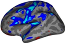
Right hemisphere mapped to a spherical surface overlaid with rh.curv curvature information:
attachment:rhsphere2-small.jpg
8.2 Automatic Cortical Parcellation BR Spherical surfaces are registered with FreeSurfer's spherical atlas, to permit both group analysis and automatic cortical parcellation. As illustrated in the surface processing pipeline diagram, the spherical surface is used as input to mris_register and mris_ca_label, which generate lh.aparc.annot or rh.aparc.annot as output, shown below:
attachment:corticalParcellation.jpg
To load this surface in tksurfer, select File -> label -> import annotation and choose lh.aparc.annot or rh.aparc.annot from the list.
A table of values(e.g. volume, surface area, average cortical thickness) for each cortical region in the annotations is computed with mris_anatomical_stats and output to:
ascii |
${SUBJECTS_DIR}/<subject name>/stats/rh.aparc.stats |
ascii |
${SUBJECTS_DIR}/<subject name>/stats/lh.aparc.stats |
8.3 Image Flattening BR The cutting and flattening process is optional and provides the user with flattened images of the whole brain or select parts (e.g. occipital lobe) of the brain. Relaxation cuts are made manually using tksurfer before flattening the surface.
The output files written by this procedure are:
surface |
${SUBJECTS_DIR}/<subject name>/surf/rh.*.patch.flat |
surface |
${SUBJECTS_DIR}/<subject name>/surf/lh.*.patch.flat |
[wiki:FsTutorial/FinalSurfEx Exercise H. View the final surfaces with tkmedit and tksurfer]
9.0 Troubleshooting
[wiki:FsTutorial/Troubleshooting Troubleshooting Guide]