|
Size: 10022
Comment:
|
← Revision 73 as of 2023-07-17 02:36:22 ⇥
Size: 12221
Comment:
|
| Deletions are marked like this. | Additions are marked like this. |
| Line 2: | Line 2: |
| [[FsTutorial|Top]] | [[FsTutorial/RunningTracula|Previous]] | [[FsTutorial/TraculaStatistics|Next]] | [[https://surfer.nmr.mgh.harvard.edu/fswiki/Tutorials|Back to list of all tutorials]] | [[FsTutorial|Back to course page]] | [[FsTutorial/RunningTracula|Previous]] | [[FsTutorial/TraculaStatistics|Next]] |
| Line 4: | Line 4: |
| = TRACULA Outputs = === Remember... === |
<<TableOfContents>> = TRACULA outputs = == Remember... == |
| Line 9: | Line 11: |
| setenv SUBJECTS_DIR $TUTORIAL_DATA/diffusion_recons cd $TUTORIAL_DATA/diffusion_tutorial |
export SUBJECTS_DIR=$TUTORIAL_DATA/tracula_tutorial/fs cd $TUTORIAL_DATA/tracula_tutorial }}} -------- == Outputs from quality assessment == The diffusion MRI contrast is designed to detect the microscopic motion of water molecules. Unfortunately this makes diffusion MRI particularly sensitive to head motion. Head motion does not result only in misalignment between consecutive DWIs, which could be corrected by registering the DWIs to each other. It can also alter the intensities of the DWIs, and this cannot be corrected by registration. The quality assessment step in TRACULA computes four measures of head motion that summarize the above effects. To see an example of these motion measures for one scan, run: {{{ cat trc/subject1/dmri/dwi_motion.txt |
| Line 13: | Line 21: |
| -------- == Ouputs From FSL's dtifit == View the ouputs of the tensor fitting from FSL's {{{dtifit}}}, one of the Pre-processing steps. Some of these outputs, e.g., the FA or MD maps, can be used for voxel-based and ROI-based group analysis. They can be viewed/analyzed in either native space or MNI space. We'll take a look at both. |
This file contains four values: the average volume-by-volume translation, the average volume-by-volume rotation, the percent of slices with excessive intensity drop-out, and the average drop-out score for slices with excessive intensity drop-out. Excessive intensity drop-out can be identified by slices that are dark, or even completely black, adjacent to normal looking slices. {{{ AvgTranslation AvgRotation PercentBadSlices AvgDropoutScore 0.304789 0.00400526 0 1 }}} |
| Line 17: | Line 27: |
| === Outputs In Native Diffusion Space === The diffusion tensor reconstruction files from FSL's {{{dtifit}}} in native space can be found in the '''dmri''' directory which was created when {{{trac-all -prep}}} was run. Let's {{{cd}}} into that directory for subject Diff001: |
Our subject was pretty well-behaved. These motion measures can be used to ensure that groups of subjects are matched with respect to head motion, or to introduce head motion as a nuissance regressor in group analyses. For more information, see [[http://www.sciencedirect.com/science/article/pii/S1053811913011312|Yendiki et al. 2014.]] If you want a more detailed break down of motion measures during the scan, run: {{{ cat trc/subject1/dmri/dwi_motion_byvol.txt }}} This file contains motion measures for each DWI volume of this subject: {{{ TranslationX TranslationY TranslationZ RotationX RotationY RotationZ PercentBadSlices AvgDropoutScore 0 0 0 0 0 0 0 1 0.00424115 -0.00629262 -0.00592024 -0.00034372 -0.000342477 4.26509e-05 0 1 -0.028909 -0.142125 0.00304372 -0.00240405 0.000228201 -0.000238103 0 1 0.0320273 -0.0183681 -0.00179705 0.000278721 -0.000196739 0.00143512 0 1 -0.0587013 0.156494 0.081299 -0.000440066 0.000288482 -0.00193024 0 1 0.0599447 0.155258 -0.024998 0.000163482 -5.79141e-06 0.00301999 0 1 -0.0945436 -0.440727 0.0647819 -0.00143778 -0.000311254 -0.00360836 0 1 0.0549738 -0.0785657 0.0209674 0.000369791 7.12276e-06 0.00315994 0 1 -0.0651216 0.259283 0.0244383 0.000830467 0.000287222 -0.00311584 0 1 ... }}} == Outputs from pre-processing: tensor fit, diffusion-to-T1 registration == Even though TRACULA relies on the ball-and-stick model instead of the tensor model to reconstruct tracts, the outputs of the tensor fit, especially anisotropy and diffusivity maps, are still useful for group analysis. In addition to the tract-based analysis that can be performed on the tract-based averages of anisotropy and diffusivity, the same maps could also be used for ROI-based or even voxel-based group analyses. The maps produced by the diffusion tensor fit can be found in the '''dmri''' directory which was created when {{{trac-all -prep}}} was run. Let's list these files for subject1: {{{ ls trc/subject1/dmri/dtifit* }}} These maps are: 1. dtifit_FA.nii.gz - Fractional anisotropy 1. dtifit_MD.nii.gz - Mean diffusivity 1. dtifit_MO.nii.gz - Mode of the anisotropy 1. dtifit_S0.nii.gz - Non-diffusion weighted (b=0) image 1. dtifit_L1.nii.gz - Primary eigenvalue of the tensor 1. dtifit_L2.nii.gz - Secondary eigenvalue of the tensor 1. dtifit_L3.nii.gz - Tertiary eigenvalue of the tensor 1. dtifit_V1.nii.gz - Primary eigenvector of the tensor 1. dtifit_V2.nii.gz - Secondary eigenvector of the tensor 1. dtifit_V3.nii.gz - Tertiary eigenvector of the tensor One can use {{{freeview}}} to view the FA map for subject1, overlaid with the subject's anatomical segmentation, which has been mapped from T1 to diffusion space. This is a good way to check the quality of the intra-subject registration. You can do this with the command below: |
| Line 21: | Line 73: |
| cd $TUTORIAL_DATA/diffusion_tutorial/Diff001/dmri | freeview trc/subject1/dmri/dtifit_FA.nii.gz \ trc/subject1/dlabel/diff/aparc+aseg.bbr.nii.gz:colormap=lut:opacity=.2 & |
| Line 24: | Line 77: |
| You can find all outputs from FSL's dtifit (tensor reconstruction) in this directory by using the {{{ls}}} command. The output maps are explained below: 1. dtifit_FA.nii.gz - Fractional Anisotropy 1. dtifit_MD.nii.gz - Mean Diffusivity 1. dtifit_MO.nii.gz - Mode of the Anisotropy 1. dtifit_S0.nii.gz - Non-Diffusion weighted image 1. dtifit_L1.nii.gz - Primary Eigen Value 1. dtifit_L2.nii.gz - Secondary Eigen Value 1. dtifit_L3.nii.gz - Tertiary Eigen Value 1. dtifit_V1.nii.gz - Primary Eigen Vector 1. dtifit_V2.nii.gz - Secondary Eigen Vector 1. dtifit_V3.nii.gz - Tertiary Eigen Vector |
Note: The above assumed that bbregister was used for the intra-subject registration. If FLIRT was used, the transformed FA map would be called {{{aparc+aseg.flt.nii.gz}}} instead. |
| Line 36: | Line 79: |
| One could use the visualization tool, freeview, to view the Fractional Anisotropy image for Diff001 in native space. You can do this with the command below: | {{attachment:fa.aparc+aseg.png}} |
| Line 38: | Line 81: |
| {{{ freeview $TUTORIAL_DATA/diffusion_tutorial/Diff001/dmri/dtifit_FA.nii.gz }}} |
Hover your mouse on different voxels throughout the image and notice the FA value change in the bottom toolbar. Look for areas of low FA and areas of high FA. Scroll through the slices using the Page Up and Page Down buttons (or up and down arrows). Feel free to change the contrast by holding down Shift and the left mouse button while dragging the mouse across the viewer window. When you are done, hit the X in the top right to close {{{freeview.}}} |
| Line 42: | Line 83: |
| {{attachment:FsTutorial/TraculaOutputs(CVS)/FA_nativespace.jpg||height="467px",width="810px"}} Hover your mouse on different voxels throughout the image and notice the FA value change in the bottom toolbar. Look for areas of low FA and areas of high FA. Scroll through the slices using the Page Up and Page Down buttons. Feel free to change the contrast by holding down Shift and the left mouse button while dragging the mouse across the viewer window. When you are done, hit the X in the top right to close freeview. All the above images are in the subject's native diffusion space. If you'd like to do a voxel-based group analysis of any of theses maps, they need to be transformed to a common space (MNI). === Outputs In MNI space === The resampling of the {{{dtifit}}} output volumes to MNI space is performed as part of the tensor-fitting step in TRACULA preprocessing. This resampling involves: * First, mapping the volumes from the individual's diffusion space to the individual's anatomical space, using either bbregister, FLIRT, or both. * Second, mapping the volumes from the individual's anatomical space to the space of the MNI template (MNI152_T1_1mm_brain by default). This uses the affine transform that is computed by the Inter-subject registration step in TRACULA preprocessing, using FSL's FLIRT. Again, among {{{dtifit}}} outputs, only the scalar maps, i.e., all outputs except the eigenvectors, are transformed to MNI space. The transformed volumes can be found in the following directory. You can find the MNI registration results in the following directory: {{{ cd $TUTORIAL_DATA/diffusion_tutorial/Diff001/dmri/mni/ }}} * To check the registration of the FA image to the MNI template in freeview, use the commands below. View the registration between the FA and the MNI template for the bbregister-ed FA version: {{{ freeview -v $FSLDIR/data/standard/MNI152_T1_1mm_brain.nii.gz \ $TUTORIAL_DATA/diffusion_tutorial/Diff001/dmri/mni/dtifit_FA.bbr.nii.gz }}} Or check the registration between the FLIRT-registered FA image and the MNI template: {{{ freeview -v $FSLDIR/data/standard/MNI152_T1_1mm_brain.nii.gz \ $TUTORIAL_DATA/diffusion_tutorial/Diff001/dmri/mni/dtifit_FA.flt.nii.gz }}} To see the correspondence between the FA in MNI space and the MNI template and check the accuracy of the registration, toggle between the two images by using the 'Alt + C' hot key. Or you can check and uncheck the box next to volume at the top of the list on the left panel. {{attachment:freeview_toggle.jpg}} |
To see the correspondence between the FA and anatomical segmentation in diffusion space and check the accuracy of the intra-subject registration, toggle between the two images by using the 'Alt + C' hot key. |
| Line 84: | Line 87: |
| {{attachment:freeview_opacity.jpg}} | {{attachment:FsTutorial/TraculaOutputs(CVS)/freeview_opacity.jpg|FsTutorial/TraculaOutputs(CVS)/freeview_opacity.jpg}} |
| Line 86: | Line 89: |
| You can make one of the views bigger by choosing the 1x1 button ( {{attachment:FreeviewGuide/FreeviewGeneralUsage/FreeviewQuickStart/layout_1x1.gif}} ). Use the orientation buttons to switch the plane ( {{attachment:FreeviewGuide/FreeviewGeneralUsage/FreeviewQuickStart/view_sagittal.gif}} , {{attachment:FreeviewGuide/FreeviewGeneralUsage/FreeviewQuickStart/view_coronal.gif}} , {{attachment:FreeviewGuide/FreeviewGeneralUsage/FreeviewQuickStart/view_axial.gif}} , {{attachment:FreeviewGuide/FreeviewGeneralUsage/FreeviewQuickStart/view_3d.gif}} ). Put your cursor at the edge of a gyrus or ventricle as a landmark before toggling back and forth between the two volumes. Scroll through the slices and try it again on a different section of the brain. Notice how accurate the registration is - the subject's anatomy should line up well between the FA map and the segmentation. When you are done, be sure to close freeview again. | |
| Line 87: | Line 91: |
| You can make one of the views bigger by choosing the 1x1 button ({{attachment:FreeviewGuide/FreeviewGeneralUsage/FreeviewQuickStart/layout_1x1.gif}}). Use the orientation buttons to switch the plane ({{attachment:FreeviewGuide/FreeviewGeneralUsage/FreeviewQuickStart/view_sagittal.gif}}, {{attachment:FreeviewGuide/FreeviewGeneralUsage/FreeviewQuickStart/view_coronal.gif}}, {{attachment:FreeviewGuide/FreeviewGeneralUsage/FreeviewQuickStart/view_axial.gif}}, {{attachment:FreeviewGuide/FreeviewGeneralUsage/FreeviewQuickStart/view_3d.gif}}). Put your cursor at the edge of a gyrus or ventricle as a landmark before toggling back and forth between the two volumes. Scroll through the slices and try it again on a different section of the brain. Notice how accurate the registration is - the anatomy in individual subject's image lines up well with the anatomy in the template's image. When you are done, be sure to close freeview again. == FSL's bedpostX Outputs == For a detailed overview of the outputs given by FSL's bedpostX please refer to the link below, http://www.fmrib.ox.ac.uk/fsl/fdt/fdt_bedpostx.html == Tractography Outputs == === Visualizing The Posterior Distribution Of A White Matter Pathway === To visualize the posterior distribution of the inferior logitudinal fasiculus tract (ILF) that was estimated using training data in MNI space, do the following: |
== Tractography outputs == === Visualizing the probability distribution of selected white-matter pathways === To visualize the posterior distribution of the inferior longitudinal fasiculus (ILF), do the following: |
| Line 101: | Line 96: |
| freeview -v $TUTORIAL_DATA/diffusion_tutorial/Diff001/dmri/dtifit_FA.nii.gz \ $TUTORIAL_DATA/diffusion_tutorial/Diff001/dpath/lh.ilf_AS_avg32_mni_flt/path.pd.nii.gz:colormap=jet:isosurface=0,0:color='yellow' \ $TUTORIAL_DATA/diffusion_tutorial/Diff001/dpath/rh.ilf_AS_avg32_mni_flt/path.pd.nii.gz:colormap=jet:isosurface=0,0:color='yellow' |
freeview -v trc/subject1/dmri/dtifit_FA.nii.gz:opacity=.6 \ trc/subject1/dpath/rh.ilf_avg16_syn_bbr/path.pd.nii.gz:colormap=heat:isosurface=1:isosurface_color=magenta:name=rh.ilf \ trc/subject1/dpath/lh.ilf_avg16_syn_bbr/path.pd.nii.gz:colormap=heat:isosurface=1:isosurface_color=yellow:name=lh.ilf |
| Line 106: | Line 101: |
| {{attachment:FsTutorial/TraculaOutputs(CVS)/ilf_pd_priormni.jpg||height="466px",width="810px"}} | Note: The above assumed that bbregister was used for the intra-subject registration and affine registration to MNI space was used for the inter-subject alignment. If anything else was used, {{{bbr}}} and {{{mni}}} would have to be adjusted accordingly. |
| Line 108: | Line 103: |
| {{attachment:lh.ilf.rh.ilf.png}} | |
| Line 109: | Line 105: |
| Click on the 3D button ( {{attachment:FreeviewGuide/FreeviewGeneralUsage/FreeviewQuickStart/view_3d.gif}} )to view isosurfaces of the left and right ILF. Use the 1x1 button ( {{attachment:FreeviewGuide/FreeviewGeneralUsage/FreeviewQuickStart/layout_1x1.gif}} ) to make it fill the window. You can rotate the image by grabbing it with the mouse and dragging. You can also move the slice planes by grabbing those and dragging them out of the way. Hold down the right mouse button and push the mouse forward for a smooth zoom inwards. | |
| Line 110: | Line 107: |
| Click on the 3D button ({{attachment:FreeviewGuide/FreeviewGeneralUsage/FreeviewQuickStart/view_3d.gif}})to view the tract. Use the 1x1 button ({{attachment:FreeviewGuide/FreeviewGeneralUsage/FreeviewQuickStart/layout_1x1.gif}}) to make it fill the window. You can rotate the image by grabbing it with the mouse and dragging. You can also move the slice planes by grabbing those and dragging them out of the way. Hold down the middle button and push the mouse forward for a smooth zoom inwards. | Here we chose to threshold the isosurface display at a very low value (1, which corresponds to the lowest probability voxels). Select either the rh.ilf or the lh.ilf volume by clicking on its name in the panel with the list of volumes on the left. You can then adjust the isosurface threshold to view higher or lower probability parts of the left or right ILF. |
| Line 112: | Line 109: |
| You can play with the isosurface threshold to change the isosurface. | {{attachment:Threshold.png|height="70px",width="270px"}} |
| Line 114: | Line 111: |
| {{attachment:FsTutorial/TraculaOutputs(CVS)/freeview_isosurface_thresh.jpg}} | This threshold also adjusts the heatmap display of the posterior distribution of the ILF in the slice (non-3D) views. You'll want to go back to one of the slice views ( {{attachment:FreeviewGuide/FreeviewGeneralUsage/FreeviewQuickStart/view_sagittal.gif}} , {{attachment:FreeviewGuide/FreeviewGeneralUsage/FreeviewQuickStart/view_coronal.gif}} , {{attachment:FreeviewGuide/FreeviewGeneralUsage/FreeviewQuickStart/view_axial.gif}} ) to see the effect. |
| Line 116: | Line 113: |
| You can also adjust the heatmap thresholds for the posterior distribution of ILF. You'll want to go back to the non-3D views ({{attachment:FreeviewGuide/FreeviewGeneralUsage/FreeviewQuickStart/view_sagittal.gif}}, {{attachment:FreeviewGuide/FreeviewGeneralUsage/FreeviewQuickStart/view_coronal.gif}}, {{attachment:FreeviewGuide/FreeviewGeneralUsage/FreeviewQuickStart/view_axial.gif}}) to see the effect. | {{attachment:heatmap.png|height="158px",width="259px"}} |
| Line 118: | Line 115: |
| {{attachment:fFsTutorial/TraculaOutputs(CVS)/reeview_heatmap_thresh.jpg}} | Close freeview when you are done. |
| Line 120: | Line 117: |
| [[FsTutorial/Diffusion|Top]] | [[FsTutorial/RunningTracula|Previous]] | [[FsTutorial/TraculaStatistics|Next]] | === Visualizing the end points of selected white-matter pathways on the cortical surface === TRACULA also saves a probability map for each endpoint of each tract and, for cortical endpoints, projects that map to the cortical surface. These are saved as !FreeSurfer '''.label''' files, which can be display on the !FreeSurfer surface reconstruction. |
| Line 122: | Line 120: |
| <<BR>><<BR>><<BR>><<BR>><<BR>><<BR>><<BR>><<BR>><<BR>><<BR>><<BR>> <<BR>><<BR>><<BR>><<BR>><<BR>><<BR>><<BR>><<BR>><<BR>><<BR>><<BR>> <<BR>><<BR>><<BR>><<BR>><<BR>><<BR>><<BR>><<BR>><<BR>><<BR>><<BR>> <<BR>><<BR>><<BR>><<BR>><<BR>><<BR>><<BR>><<BR>><<BR>><<BR>><<BR>> <<BR>><<BR>><<BR>><<BR>><<BR>><<BR>><<BR>><<BR>><<BR>><<BR>><<BR>> <<BR>><<BR>><<BR>><<BR>><<BR>><<BR>><<BR>><<BR>><<BR>><<BR>><<BR>> <<BR>><<BR>><<BR>><<BR>><<BR>><<BR>><<BR>><<BR>><<BR>><<BR>><<BR>> <<BR>><<BR>><<BR>><<BR>><<BR>><<BR>><<BR>><<BR>><<BR>><<BR>><<BR>> <<BR>><<BR>><<BR>><<BR>><<BR>><<BR>><<BR>><<BR>><<BR>><<BR>><<BR>> <<BR>><<BR>><<BR>><<BR>><<BR>><<BR>><<BR>><<BR>><<BR>><<BR>><<BR>> <<BR>><<BR>><<BR>><<BR>><<BR>><<BR>><<BR>><<BR>><<BR>><<BR>><<BR>> ''' DO NOT DO THE BELOW''' === Visualizing The Posterior Distribution Of All Reconstructed Tracts === Tracula also outputs a merged 4D volume, which is a concatenation of the estimated distribution of all the tracts. To visualize all tracts reconstructed using TRACULA, do the following: |
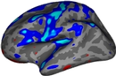
To display the cortical endpoints of the left uncinate fasciculus (UF) on the inflated surface, run: |
| Line 137: | Line 122: |
| freeview -tv $TUTORIAL_DATA/diffusion_tutorial/Diff001/dpath/merged_avg32_mni_flt.mgz \ -v $TUTORIAL_DATA/diffusion_tutorial/Diff001/dmri/dtifit_FA.nii.gz |
freeview -f $SUBJECTS_DIR/subject1/surf/lh.inflated:curvature_method=binary:label=trc/subject1/dpath/lh.uf_avg16_syn_bbr/endpt1.surf.label:label_color=green:label=trc/subject1/dpath/lh.uf_avg16_syn_bbr/endpt2.surf.label:label_color=yellow |
| Line 140: | Line 124: |
| {{attachment:merged_tracts.jpg}} The lower-left corner of the freeview display gives the color lookup table for all the tracts. The tracts in the merged volume are displayed at 20% of their maximum threshold, by default. Hence the posterior distribution of some of tracts may not be displayed in its entirety. To look at the complete path distribution of a specific tract in non-3D views, you can play with the threshold values again: {{attachment:freeview_isosurface_thresh.jpg}} The threshold for each tract can also be adjusted in the 3D view by selecting a specific tract from the lookup table {{attachment:select_tract.jpg}} and adjusting the threshold button {{attachment:4d_tract_thresh.jpg}} at the bottom of the freeview diplay panel to view the 3D distribution of a tract at various thresholds (between 1 and 100). |
{{attachment:lh.uf.endpts.png}} In the command above, we chose to display the frontal endpoint label ({{{endpt1}}}) as green, and the temporal endpoint label ({{{endpt2}}})as yellow. You can work with these labels just as you would with any other !FreeSurfer surface label (see [[FsTutorial/AnatomicalROI#Labelfiles|ROI analysis]] tutorial). When you are done, close freeview. === Visualizing the probability distributions of all white-matter pathways simultaneously === TRACULA also outputs a merged 4D volume, which is a concatenation of the probability distributions of all the pathways that were reconstructed. To visualize all pathways at once, open this merged 4D volume in {{{freeview}}} using the '''-tv''' (tract volume) option: {{{ freeview -v trc/subject1/dmri/dtifit_FA.nii.gz:opacity=.6 \ -tv trc/subject1/dpath/merged_avg16_syn_bbr.mgz & }}} The screenshot below shows the ventral surface of the brain in the 3D view: {{attachment:merged42.png}} The panel in the lower-left corner of the freeview display gives the color lookup table for all the tracts. When we use the '''-tv''' option to visualize the merged tract volume, each tract in this volume is displayed at 20% of its peak probability, by default. This is a higher threshold that what we used to visualize the ILF in the previous example. This higher threshold allows a larger number of tracts to be visible, but it means that the posterior distribution of every individual tract is not displayed in its entirety. The threshold at which each tract is displayed in both the 3D and non-3D views can be adjusted by selecting a specific tract from the panel with the tract lookup table on the left, and adjusting the threshold slider under the panel. {{attachment:4d_tract_thresh.jpg||height="30px",width="358px"}} When you are done, close freeview. |
| Line 145: | Line 150: |
| [[FsTutorial/Diffusion|Top]] | [[FsTutorial/RunningTracula|Previous]] | [[FsTutorial/TraculaStatistics|Next]] | -------- = Summary = By the end of this page, you should know how to: * Check head motion measures * View the maps output by the tensor fit (''e.g.,'' FA) in freeview * Overlay these with the anatomical segmentation to check the intra-subject registration * Visualize and manipulate tractography outputs in freeview [[https://surfer.nmr.mgh.harvard.edu/fswiki/Tutorials|Back to list of all tutorials]] | [[FsTutorial|Back to course page]] | [[FsTutorial/RunningTracula|Previous]] | [[FsTutorial/TraculaStatistics|Next]] |
Back to list of all tutorials | Back to course page | Previous | Next
Contents
TRACULA outputs
Remember...
For each new terminal that you open, you must do:
export SUBJECTS_DIR=$TUTORIAL_DATA/tracula_tutorial/fs cd $TUTORIAL_DATA/tracula_tutorial
Outputs from quality assessment
The diffusion MRI contrast is designed to detect the microscopic motion of water molecules. Unfortunately this makes diffusion MRI particularly sensitive to head motion. Head motion does not result only in misalignment between consecutive DWIs, which could be corrected by registering the DWIs to each other. It can also alter the intensities of the DWIs, and this cannot be corrected by registration. The quality assessment step in TRACULA computes four measures of head motion that summarize the above effects. To see an example of these motion measures for one scan, run:
cat trc/subject1/dmri/dwi_motion.txt
This file contains four values: the average volume-by-volume translation, the average volume-by-volume rotation, the percent of slices with excessive intensity drop-out, and the average drop-out score for slices with excessive intensity drop-out. Excessive intensity drop-out can be identified by slices that are dark, or even completely black, adjacent to normal looking slices.
AvgTranslation AvgRotation PercentBadSlices AvgDropoutScore
0.304789 0.00400526 0 1
Our subject was pretty well-behaved. These motion measures can be used to ensure that groups of subjects are matched with respect to head motion, or to introduce head motion as a nuissance regressor in group analyses. For more information, see Yendiki et al. 2014.
If you want a more detailed break down of motion measures during the scan, run:
cat trc/subject1/dmri/dwi_motion_byvol.txt
This file contains motion measures for each DWI volume of this subject:
TranslationX TranslationY TranslationZ RotationX RotationY RotationZ PercentBadSlices AvgDropoutScore
0 0 0 0 0 0 0 1
0.00424115 -0.00629262 -0.00592024 -0.00034372 -0.000342477 4.26509e-05 0 1
-0.028909 -0.142125 0.00304372 -0.00240405 0.000228201 -0.000238103 0 1
0.0320273 -0.0183681 -0.00179705 0.000278721 -0.000196739 0.00143512 0 1
-0.0587013 0.156494 0.081299 -0.000440066 0.000288482 -0.00193024 0 1
0.0599447 0.155258 -0.024998 0.000163482 -5.79141e-06 0.00301999 0 1
-0.0945436 -0.440727 0.0647819 -0.00143778 -0.000311254 -0.00360836 0 1
0.0549738 -0.0785657 0.0209674 0.000369791 7.12276e-06 0.00315994 0 1
-0.0651216 0.259283 0.0244383 0.000830467 0.000287222 -0.00311584 0 1
...
Outputs from pre-processing: tensor fit, diffusion-to-T1 registration
Even though TRACULA relies on the ball-and-stick model instead of the tensor model to reconstruct tracts, the outputs of the tensor fit, especially anisotropy and diffusivity maps, are still useful for group analysis. In addition to the tract-based analysis that can be performed on the tract-based averages of anisotropy and diffusivity, the same maps could also be used for ROI-based or even voxel-based group analyses.
The maps produced by the diffusion tensor fit can be found in the dmri directory which was created when trac-all -prep was run. Let's list these files for subject1:
ls trc/subject1/dmri/dtifit*
These maps are:
- dtifit_FA.nii.gz - Fractional anisotropy
- dtifit_MD.nii.gz - Mean diffusivity
- dtifit_MO.nii.gz - Mode of the anisotropy
- dtifit_S0.nii.gz - Non-diffusion weighted (b=0) image
- dtifit_L1.nii.gz - Primary eigenvalue of the tensor
- dtifit_L2.nii.gz - Secondary eigenvalue of the tensor
- dtifit_L3.nii.gz - Tertiary eigenvalue of the tensor
- dtifit_V1.nii.gz - Primary eigenvector of the tensor
- dtifit_V2.nii.gz - Secondary eigenvector of the tensor
- dtifit_V3.nii.gz - Tertiary eigenvector of the tensor
One can use freeview to view the FA map for subject1, overlaid with the subject's anatomical segmentation, which has been mapped from T1 to diffusion space. This is a good way to check the quality of the intra-subject registration. You can do this with the command below:
freeview trc/subject1/dmri/dtifit_FA.nii.gz \
         trc/subject1/dlabel/diff/aparc+aseg.bbr.nii.gz:colormap=lut:opacity=.2 &
Note: The above assumed that bbregister was used for the intra-subject registration. If FLIRT was used, the transformed FA map would be called aparc+aseg.flt.nii.gz instead.

Hover your mouse on different voxels throughout the image and notice the FA value change in the bottom toolbar. Look for areas of low FA and areas of high FA. Scroll through the slices using the Page Up and Page Down buttons (or up and down arrows). Feel free to change the contrast by holding down Shift and the left mouse button while dragging the mouse across the viewer window. When you are done, hit the X in the top right to close freeview.
To see the correspondence between the FA and anatomical segmentation in diffusion space and check the accuracy of the intra-subject registration, toggle between the two images by using the 'Alt + C' hot key.
Alternatively, you can adjust the opacity:
/freeview_opacity.jpg")
You can make one of the views bigger by choosing the 1x1 button (  ). Use the orientation buttons to switch the plane (
  ,
,  ,
,  ,
,  ). Put your cursor at the edge of a gyrus or ventricle as a landmark before toggling back and forth between the two volumes. Scroll through the slices and try it again on a different section of the brain. Notice how accurate the registration is - the subject's anatomy should line up well between the FA map and the segmentation. When you are done, be sure to close freeview again.
Tractography outputs
Visualizing the probability distribution of selected white-matter pathways
To visualize the posterior distribution of the inferior longitudinal fasiculus (ILF), do the following:
freeview -v trc/subject1/dmri/dtifit_FA.nii.gz:opacity=.6 \
            trc/subject1/dpath/rh.ilf_avg16_syn_bbr/path.pd.nii.gz:colormap=heat:isosurface=1:isosurface_color=magenta:name=rh.ilf \
            trc/subject1/dpath/lh.ilf_avg16_syn_bbr/path.pd.nii.gz:colormap=heat:isosurface=1:isosurface_color=yellow:name=lh.ilf
Note: The above assumed that bbregister was used for the intra-subject registration and affine registration to MNI space was used for the inter-subject alignment. If anything else was used, bbr and mni would have to be adjusted accordingly.

Click on the 3D button ( )to view isosurfaces of the left and right ILF. Use the 1x1 button ( ) to make it fill the window. You can rotate the image by grabbing it with the mouse and dragging. You can also move the slice planes by grabbing those and dragging them out of the way. Hold down the right mouse button and push the mouse forward for a smooth zoom inwards.
Here we chose to threshold the isosurface display at a very low value (1, which corresponds to the lowest probability voxels). Select either the rh.ilf or the lh.ilf volume by clicking on its name in the panel with the list of volumes on the left. You can then adjust the isosurface threshold to view higher or lower probability parts of the left or right ILF.

This threshold also adjusts the heatmap display of the posterior distribution of the ILF in the slice (non-3D) views. You'll want to go back to one of the slice views ( , , ) to see the effect.

Close freeview when you are done.
Visualizing the end points of selected white-matter pathways on the cortical surface
TRACULA also saves a probability map for each endpoint of each tract and, for cortical endpoints, projects that map to the cortical surface. These are saved as FreeSurfer .label files, which can be display on the FreeSurfer surface reconstruction.
To display the cortical endpoints of the left uncinate fasciculus (UF) on the inflated surface, run:
freeview -f $SUBJECTS_DIR/subject1/surf/lh.inflated:curvature_method=binary:label=trc/subject1/dpath/lh.uf_avg16_syn_bbr/endpt1.surf.label:label_color=green:label=trc/subject1/dpath/lh.uf_avg16_syn_bbr/endpt2.surf.label:label_color=yellow

In the command above, we chose to display the frontal endpoint label (endpt1) as green, and the temporal endpoint label (endpt2)as yellow. You can work with these labels just as you would with any other FreeSurfer surface label (see ROI analysis tutorial). When you are done, close freeview.
Visualizing the probability distributions of all white-matter pathways simultaneously
TRACULA also outputs a merged 4D volume, which is a concatenation of the probability distributions of all the pathways that were reconstructed. To visualize all pathways at once, open this merged 4D volume in freeview using the -tv (tract volume) option:
freeview -v  trc/subject1/dmri/dtifit_FA.nii.gz:opacity=.6 \
         -tv trc/subject1/dpath/merged_avg16_syn_bbr.mgz &
The screenshot below shows the ventral surface of the brain in the 3D view:

The panel in the lower-left corner of the freeview display gives the color lookup table for all the tracts. When we use the -tv option to visualize the merged tract volume, each tract in this volume is displayed at 20% of its peak probability, by default. This is a higher threshold that what we used to visualize the ILF in the previous example. This higher threshold allows a larger number of tracts to be visible, but it means that the posterior distribution of every individual tract is not displayed in its entirety.
The threshold at which each tract is displayed in both the 3D and non-3D views can be adjusted by selecting a specific tract from the panel with the tract lookup table on the left, and adjusting the threshold slider under the panel.

When you are done, close freeview.
Now that you've seen what the output looks like, you can take a look at the resulting stats for each tract by clicking on the Next button below.
Summary
By the end of this page, you should know how to:
- Check head motion measures
View the maps output by the tensor fit (e.g., FA) in freeview
- Overlay these with the anatomical segmentation to check the intra-subject registration
- Visualize and manipulate tractography outputs in freeview
Back to list of all tutorials | Back to course page | Previous | Next