|
Size: 72234
Comment:
|
Size: 16205
Comment:
|
| Deletions are marked like this. | Additions are marked like this. |
| Line 1: | Line 1: |
| = 3D Scanning Documentation = == Table of Contents == === Chapter === [[#_Toc121358088|1. Einscan Turntable Protocol]] |
= Photo Reconstruction Documentation = <<TableOfContents>><<BR>><<BR>> |
| Line 6: | Line 4: |
| . [[#_Toc121358089|Scanner Setup]] | == Citation == If you use these tools in your analysis, please cite: * Gazula, H., Tregidgo, H.F., Billot, B., Balbastre, Y., Williams Ramirez, J., Herisse, R., Deden-Binder, L.J., Casamitjana, A., Melief, E.J., Latimer, C.S. and Kilgore, M.D., 2024. Machine learning of dissection photographs and surface scanning for quantitative 3D neuropathology. Elife, 12, p.RP91398. [[https://doi.org/10.7554/eLife.91398.4 | doi]] |
| Line 8: | Line 8: |
| [[#_Toc121358091|Running the Scan]] [[#_Toc121358092|Editing and Saving Data]] [[#_Toc121358093|2. Preparing Your Slab Data]] [[#_Toc121358094|3. Image Correction]] '' '' [[#_Toc121358095|4. Binarizing Your Image]] '' '' [[#_Toc121358096|5. Connected Components]] '' '' [[#_Toc121358097|6. Photo Reconstruction]] |
[[https://www.youtube.com/watch?v=wo5meYRaGUY|Click here for a video with an overview of the method]]<<BR>> {{attachment:video_screenshot.png||width="666",}} <<BR>><<BR>> |
| Line 29: | Line 13: |
| This manual will provide step-by-step instructions on utilizing the EinScan Pro HD scanner, recommended preparation of tissue slabs after scanning, and outline the data processing pipeline to finalize a 3D reconstruction of brain slab images using a reference surface. | This manual provides an end-to-end guide for using the tools available on FreeSurfer to reconstruct dissection photographs of brain slabs into a 3D-reconstruction for quantitative analysis. Reconstructions are done by registering photographs to a 3D reference like an MRI, a post-mortem surface scan, or an atlas. The guide touches on aquisition of surface scans prior to slabbing, preparing tissue slabs for gross photography, and how to preprocess photographs using the dissection_photo graphical user interface.<<BR>><<BR>> |
| Line 31: | Line 15: |
| = 1. Einscan Turntable Protocol = This section will cover our standard operating procedure for scanning fixed tissue samples in the Massachusetts General Hospital (MGH). In the setup, we use an EinScan Pro HD scanner with the ‘industrial pack,’ which includes an additional turntable and tripod. A good surface scan is critical for accurately reconstructing the tissue slabs, as it is used as the reference to which the slabs are registered and deformed into. Later sections will cover surface mesh quality assessment and what to look for in a scan. |
== Requirements == * The latest FreeSurfer development version sourced in your terminal. * Model files (downloaded once): * the [[https://ftp.nmr.mgh.harvard.edu/pub/dist/lcnpublic/dist/dissection_photo_model/photo_imputation_unet.pth|reconstruction model]] downloaded, into `$FREESURFER_HOME/models` * A CUDA enabled graphics card is optional: segmentation and reconstruction are much faster with one. |
| Line 34: | Line 21: |
| == Scanner Setup == To set up the turntable and scanner, we adjust the tripod closely to the tissue while maintaining a clear view of the full turntable plate. Having the scanner not too far from the tissue will yield the best results. When using ‘Handheld’ mode, SHINING3D software will guide the user on the scanner distance. On the table, the scanner is adjusted to approximately 45˚, 8-10 inches from the turntable. Both the scanner and turntable are connected to the computer via USB and external power. |
= Part 1: Acquisition = |
| Line 37: | Line 23: |
| {{[[[[[[file:////Users/Jon/Library/Group%20Containers/UBF8T346G9.Office/TemporaryItems/msohtmlclip/clip_image001.png|A|file:////Users/Jon/Library/Group%20Containers/UBF8T346G9.Office/TemporaryItems/msohtmlclip/clip_image001.png|A|file:////Users/Jon/Library/Group%20Containers/UBF8T346G9.Office/TemporaryItems/msohtmlclip/clip_image001.png|A|file:////Users/Jon/Library/Group%20Containers/UBF8T346G9.Office/TemporaryItems/msohtmlclip/clip_image001.png|A|file:////Users/Jon/Library/Group%20Containers/UBF8T346G9.Office/TemporaryItems/msohtmlclip/clip_image001.png|A|file:////Users/Jon/Library/Group%20Containers/UBF8T346G9.Office/TemporaryItems/msohtmlclip/clip_image001.png|A|file:////Users/Jon/Library/Group%20Containers/UBF8T346G9.Office/TemporaryItems/msohtmlclip/clip_image001.png|A|file:////Users/Jon/Library/Group%20Containers/UBF8T346G9.Office/TemporaryItems/msohtmlclip/clip_image001.png|A]]]]]] picture containing indoor | == Surface scanning == A surface scan of the specimen, taken before it is slabbed after the cerebellum is sectioned. The full scanning protocol is available on its own page: '''[[PhotoTools Surface Scanning|Surface Scanning Protocol]]'''. |
| Line 39: | Line 26: |
| Description automatically generated|width="363",height="257"}} Scanner setup for turntable scan Next, we launch the most up-to-date Shining3D software for the Einscan Pro HD. Software for all EinsScan 3D scanners can be found at [[https://www.einscan.com/support/download/|einscan.com/support/download/]]. Next, a menu will prompt a selection for the type of scan, fixed scan (using the turntable), handheld HD scan, or handheld rapid scan. We select “fixed scan” to use the turntable add-on and create a new “Non-texture Scan” project. {{[[[[[[file:////Users/Jon/Library/Group%20Containers/UBF8T346G9.Office/TemporaryItems/msohtmlclip/clip_image002.png|Graphical|file:////Users/Jon/Library/Group%20Containers/UBF8T346G9.Office/TemporaryItems/msohtmlclip/clip_image002.png|Graphical|file:////Users/Jon/Library/Group%20Containers/UBF8T346G9.Office/TemporaryItems/msohtmlclip/clip_image002.png|Graphical|file:////Users/Jon/Library/Group%20Containers/UBF8T346G9.Office/TemporaryItems/msohtmlclip/clip_image002.png|Graphical|file:////Users/Jon/Library/Group%20Containers/UBF8T346G9.Office/TemporaryItems/msohtmlclip/clip_image002.png|Graphical|file:////Users/Jon/Library/Group%20Containers/UBF8T346G9.Office/TemporaryItems/msohtmlclip/clip_image002.png|Graphical|file:////Users/Jon/Library/Group%20Containers/UBF8T346G9.Office/TemporaryItems/msohtmlclip/clip_image002.png|Graphical|file:////Users/Jon/Library/Group%20Containers/UBF8T346G9.Office/TemporaryItems/msohtmlclip/clip_image002.png|Graphical]]]]]] user interface, application Description automatically generated|border="0",width="277",height="195"}} Texture settings prompt when creating a new project. At this point, the main scan menu should be on the screen, where we can customize different parameters for scan acquisition. On the left-hand side of the screen, there is a preview of the scanner’s field of view. {{[[[[[[file:////Users/Jon/Library/Group%20Containers/UBF8T346G9.Office/TemporaryItems/msohtmlclip/clip_image004.png|A|file:////Users/Jon/Library/Group%20Containers/UBF8T346G9.Office/TemporaryItems/msohtmlclip/clip_image004.png|A|file:////Users/Jon/Library/Group%20Containers/UBF8T346G9.Office/TemporaryItems/msohtmlclip/clip_image004.png|A|file:////Users/Jon/Library/Group%20Containers/UBF8T346G9.Office/TemporaryItems/msohtmlclip/clip_image004.png|A|file:////Users/Jon/Library/Group%20Containers/UBF8T346G9.Office/TemporaryItems/msohtmlclip/clip_image004.png|A|file:////Users/Jon/Library/Group%20Containers/UBF8T346G9.Office/TemporaryItems/msohtmlclip/clip_image004.png|A|file:////Users/Jon/Library/Group%20Containers/UBF8T346G9.Office/TemporaryItems/msohtmlclip/clip_image004.png|A|file:////Users/Jon/Library/Group%20Containers/UBF8T346G9.Office/TemporaryItems/msohtmlclip/clip_image004.png|A]]]]]] screenshot of a computer Description automatically generated with medium confidence|border="0",width="390",height="206"}} Main scan menu In the Scan Setting menu, ensure the “with Turntable” box is checked and the align mode is set to Features. The alignment mode “Turntable Coded Targets” is not used because tissue can slide as the turntable changes orientation. Sliding can be especially present when scanning the medial wall and can be helped by gently patting the tissue with a linen towel to remove some excess fixative on the tissue. When using the handheld mode, we highly recommend using markers which can vastly improve scanning speed and user experience. Turntable steps determine how many scans will be acquired and stitched for this session. Higher numbers can lead to more accurate data but can increase scan time. We set turntable steps to 48, which we consider a good balance between acquisition time and scan quality. For handheld scans, we use the parameters: * Texture: Non-texture scan * Mode of alignment: hybrid * Operation mode: classic (scanning speed: 15 fps) * Resolution: high (0.5mm) == Sample Setup == We place a glass sheet atop to protect the turntable and ease cleanup. The glass sheet contains markers that can aid tracking in handheld scans but will not be used with the feature alignment mode. The sample is placed in the middle of the turntable so that the scanner gets the best view of the sample as it rotates. Occluding the turntable markers will also affect the stitching of scans if the scan is set to “Turntable Coded Targets.” When doing a handheld scan, make sure the sample is not covering the placed markers on the glass sheet. Note the sample does not include the cerebellum. {{[[[[[[file:////Users/Jon/Library/Group%20Containers/UBF8T346G9.Office/TemporaryItems/msohtmlclip/clip_image006.png|A|file:////Users/Jon/Library/Group%20Containers/UBF8T346G9.Office/TemporaryItems/msohtmlclip/clip_image006.png|A|file:////Users/Jon/Library/Group%20Containers/UBF8T346G9.Office/TemporaryItems/msohtmlclip/clip_image006.png|A|file:////Users/Jon/Library/Group%20Containers/UBF8T346G9.Office/TemporaryItems/msohtmlclip/clip_image006.png|A|file:////Users/Jon/Library/Group%20Containers/UBF8T346G9.Office/TemporaryItems/msohtmlclip/clip_image006.png|A|file:////Users/Jon/Library/Group%20Containers/UBF8T346G9.Office/TemporaryItems/msohtmlclip/clip_image006.png|A|file:////Users/Jon/Library/Group%20Containers/UBF8T346G9.Office/TemporaryItems/msohtmlclip/clip_image006.png|A|file:////Users/Jon/Library/Group%20Containers/UBF8T346G9.Office/TemporaryItems/msohtmlclip/clip_image006.png|A]]]]]] picture containing text, dish Description automatically generated|border="0",width="215",height="220"}} Sample placement on the turntable with sample lateral side down Two scan projects are created for all samples on opposite sides. For hemispheres, we first acquire a scan with the sample medial side down. Next, the hemisphere is flipped to be lateral side down, and the tissue is more likely to shift when the turntable steps. To reduce sample movement, we wipe down excess fixative on the sheet of glass to improve traction. Whole Brains are scanned upright (brain stem down) and upside down. Although these types of samples do not tend to move during the scan, they can deform between being upright versus upside down, which can lead to issues aligning the two sets of point clouds. ''Tip'': Samples should have the cerebellum removed before acquisition. The cerebellum is not considered in the reconstruction, including it present in the scan will lead to incorrect slice reconstruction. {{[[[[[[file:////Users/Jon/Library/Group%20Containers/UBF8T346G9.Office/TemporaryItems/msohtmlclip/clip_image008.png|A|file:////Users/Jon/Library/Group%20Containers/UBF8T346G9.Office/TemporaryItems/msohtmlclip/clip_image008.png|A|file:////Users/Jon/Library/Group%20Containers/UBF8T346G9.Office/TemporaryItems/msohtmlclip/clip_image008.png|A|file:////Users/Jon/Library/Group%20Containers/UBF8T346G9.Office/TemporaryItems/msohtmlclip/clip_image008.png|A|file:////Users/Jon/Library/Group%20Containers/UBF8T346G9.Office/TemporaryItems/msohtmlclip/clip_image008.png|A|file:////Users/Jon/Library/Group%20Containers/UBF8T346G9.Office/TemporaryItems/msohtmlclip/clip_image008.png|A|file:////Users/Jon/Library/Group%20Containers/UBF8T346G9.Office/TemporaryItems/msohtmlclip/clip_image008.png|A|file:////Users/Jon/Library/Group%20Containers/UBF8T346G9.Office/TemporaryItems/msohtmlclip/clip_image008.png|A]]]]]] close-up of a brain Description automatically generated with medium confidence|border="0",width="275",height="239"}} Scan incorrectly including the cerebellum. . '' '' |
<<BR>> |
| Line 92: | Line 29: |
| ''Handheld Scanning'' | = Preparing Slab Data = The following guidelines should be followed when preparing slab images for optimal results. <<BR>> |
| Line 94: | Line 32: |
| Handheld mode is also an option, particularly for fresh tissue, due to the tissue being unable to maintain its shape. It cannot be flipped for two-sided scans. In this mode, a transparent surface can be used to scan both sides of the sample without having to shift the easily deformable tissue. | == Guidelines for Brain Slab Image Acquisition == There are some important requirements for the photographic setup of the brain slabs to ensure the best results. |
| Line 96: | Line 35: |
| {{[[[[[[file:////Users/Jon/Library/Group%20Containers/UBF8T346G9.Office/TemporaryItems/msohtmlclip/clip_image010.png|A|file:////Users/Jon/Library/Group%20Containers/UBF8T346G9.Office/TemporaryItems/msohtmlclip/clip_image010.png|A|file:////Users/Jon/Library/Group%20Containers/UBF8T346G9.Office/TemporaryItems/msohtmlclip/clip_image010.png|A|file:////Users/Jon/Library/Group%20Containers/UBF8T346G9.Office/TemporaryItems/msohtmlclip/clip_image010.png|A|file:////Users/Jon/Library/Group%20Containers/UBF8T346G9.Office/TemporaryItems/msohtmlclip/clip_image010.png|A|file:////Users/Jon/Library/Group%20Containers/UBF8T346G9.Office/TemporaryItems/msohtmlclip/clip_image010.png|A|file:////Users/Jon/Library/Group%20Containers/UBF8T346G9.Office/TemporaryItems/msohtmlclip/clip_image010.png|A|file:////Users/Jon/Library/Group%20Containers/UBF8T346G9.Office/TemporaryItems/msohtmlclip/clip_image010.png|A]]]]]] picture containing floor, indoor, kitchen, appliance | Use a high-contrast background that stands out in uniform contrast to the brain slabs, such as a solid black background. This will make slabs are easier to segment downstream. Using a complex background with color similar to your brain slabs, will lead to a more manual intervention such as having to manually trace contours, which is not only time-consuming but also non-reproducible.<<BR>> |
| Line 98: | Line 37: |
| Description automatically generated|border="0",width="205",height="191"}} Example of a handheld scan setup == Running the Scan == In the scan workspace, the preview window is used to center the tissue sample in the camera view. Set the red crosshairs to the middle of the sample for full coverage of the tissue as the turntable moves. {{[[[[[[file:////Users/Jon/Library/Group%20Containers/UBF8T346G9.Office/TemporaryItems/msohtmlclip/clip_image011.png|A|file:////Users/Jon/Library/Group%20Containers/UBF8T346G9.Office/TemporaryItems/msohtmlclip/clip_image011.png|A|file:////Users/Jon/Library/Group%20Containers/UBF8T346G9.Office/TemporaryItems/msohtmlclip/clip_image011.png|A|file:////Users/Jon/Library/Group%20Containers/UBF8T346G9.Office/TemporaryItems/msohtmlclip/clip_image011.png|A|file:////Users/Jon/Library/Group%20Containers/UBF8T346G9.Office/TemporaryItems/msohtmlclip/clip_image011.png|A|file:////Users/Jon/Library/Group%20Containers/UBF8T346G9.Office/TemporaryItems/msohtmlclip/clip_image011.png|A|file:////Users/Jon/Library/Group%20Containers/UBF8T346G9.Office/TemporaryItems/msohtmlclip/clip_image011.png|A|file:////Users/Jon/Library/Group%20Containers/UBF8T346G9.Office/TemporaryItems/msohtmlclip/clip_image011.png|A]]]]]] screenshot of a computer Description automatically generated with medium confidence|border="0",width="194",height="146"}} Scanner preview The camera exposure has a large effect on scan quality. Incorrect exposure can lead to noisier surfaces in the resulting scan point clouds. Exposure is adjusted in the main scan menu on the slider under the camera preview screen. ''' {{[[[[[[file:////Users/Jon/Library/Group%20Containers/UBF8T346G9.Office/TemporaryItems/msohtmlclip/clip_image012.png|Text|file:////Users/Jon/Library/Group%20Containers/UBF8T346G9.Office/TemporaryItems/msohtmlclip/clip_image012.png|Text|file:////Users/Jon/Library/Group%20Containers/UBF8T346G9.Office/TemporaryItems/msohtmlclip/clip_image012.png|Text|file:////Users/Jon/Library/Group%20Containers/UBF8T346G9.Office/TemporaryItems/msohtmlclip/clip_image012.png|Text|file:////Users/Jon/Library/Group%20Containers/UBF8T346G9.Office/TemporaryItems/msohtmlclip/clip_image012.png|Text|file:////Users/Jon/Library/Group%20Containers/UBF8T346G9.Office/TemporaryItems/msohtmlclip/clip_image012.png|Text|file:////Users/Jon/Library/Group%20Containers/UBF8T346G9.Office/TemporaryItems/msohtmlclip/clip_image012.png|Text|file:////Users/Jon/Library/Group%20Containers/UBF8T346G9.Office/TemporaryItems/msohtmlclip/clip_image012.png|Text]]]]]] ''' '''Description automatically generated with low confidence|border="0",width="253",height="42"}} ''' Scanner exposure slider To determine if the sample is not exposed appropriately, the preview window will show bright regions with red. The slider is set to an exposure where there are some but not many red regions. To avoid any issues with exposure, sometimes we use HDR mode, which can be set in the Scan Settings menu for fixed turntable scans. i. Overexposed (red filter on sample + bright image) {{[[[[[[file:////Users/Jon/Library/Group%20Containers/UBF8T346G9.Office/TemporaryItems/msohtmlclip/clip_image014.png|Graphical|file:////Users/Jon/Library/Group%20Containers/UBF8T346G9.Office/TemporaryItems/msohtmlclip/clip_image014.png|Graphical|file:////Users/Jon/Library/Group%20Containers/UBF8T346G9.Office/TemporaryItems/msohtmlclip/clip_image014.png|Graphical|file:////Users/Jon/Library/Group%20Containers/UBF8T346G9.Office/TemporaryItems/msohtmlclip/clip_image014.png|Graphical|file:////Users/Jon/Library/Group%20Containers/UBF8T346G9.Office/TemporaryItems/msohtmlclip/clip_image014.png|Graphical|file:////Users/Jon/Library/Group%20Containers/UBF8T346G9.Office/TemporaryItems/msohtmlclip/clip_image014.png|Graphical|file:////Users/Jon/Library/Group%20Containers/UBF8T346G9.Office/TemporaryItems/msohtmlclip/clip_image014.png|Graphical|file:////Users/Jon/Library/Group%20Containers/UBF8T346G9.Office/TemporaryItems/msohtmlclip/clip_image014.png|Graphical]]]]]] user interface Description automatically generated with low confidence|border="0",width="98",height="111"}} ii. Underexposed (black filter on sample + dark image) {{[[[[[[file:////Users/Jon/Library/Group%20Containers/UBF8T346G9.Office/TemporaryItems/msohtmlclip/clip_image015.png|A|file:////Users/Jon/Library/Group%20Containers/UBF8T346G9.Office/TemporaryItems/msohtmlclip/clip_image015.png|A|file:////Users/Jon/Library/Group%20Containers/UBF8T346G9.Office/TemporaryItems/msohtmlclip/clip_image015.png|A|file:////Users/Jon/Library/Group%20Containers/UBF8T346G9.Office/TemporaryItems/msohtmlclip/clip_image015.png|A|file:////Users/Jon/Library/Group%20Containers/UBF8T346G9.Office/TemporaryItems/msohtmlclip/clip_image015.png|A|file:////Users/Jon/Library/Group%20Containers/UBF8T346G9.Office/TemporaryItems/msohtmlclip/clip_image015.png|A|file:////Users/Jon/Library/Group%20Containers/UBF8T346G9.Office/TemporaryItems/msohtmlclip/clip_image015.png|A|file:////Users/Jon/Library/Group%20Containers/UBF8T346G9.Office/TemporaryItems/msohtmlclip/clip_image015.png|A]]]]]] picture containing text Description automatically generated|border="0",width="101",height="130"}} iii. Sufficient exposure (can see sample, markers, decent contrast) {{[[[[[[file:////Users/Jon/Library/Group%20Containers/UBF8T346G9.Office/TemporaryItems/msohtmlclip/clip_image016.png|Shape|file:////Users/Jon/Library/Group%20Containers/UBF8T346G9.Office/TemporaryItems/msohtmlclip/clip_image016.png|Shape|file:////Users/Jon/Library/Group%20Containers/UBF8T346G9.Office/TemporaryItems/msohtmlclip/clip_image016.png|Shape|file:////Users/Jon/Library/Group%20Containers/UBF8T346G9.Office/TemporaryItems/msohtmlclip/clip_image016.png|Shape|file:////Users/Jon/Library/Group%20Containers/UBF8T346G9.Office/TemporaryItems/msohtmlclip/clip_image016.png|Shape|file:////Users/Jon/Library/Group%20Containers/UBF8T346G9.Office/TemporaryItems/msohtmlclip/clip_image016.png|Shape|file:////Users/Jon/Library/Group%20Containers/UBF8T346G9.Office/TemporaryItems/msohtmlclip/clip_image016.png|Shape|file:////Users/Jon/Library/Group%20Containers/UBF8T346G9.Office/TemporaryItems/msohtmlclip/clip_image016.png|Shape]]]]]] Description automatically generated with low confidence|border="0",width="22",height="22"}} {{[[[[[[file:////Users/Jon/Library/Group%20Containers/UBF8T346G9.Office/TemporaryItems/msohtmlclip/clip_image017.png|A|file:////Users/Jon/Library/Group%20Containers/UBF8T346G9.Office/TemporaryItems/msohtmlclip/clip_image017.png|A|file:////Users/Jon/Library/Group%20Containers/UBF8T346G9.Office/TemporaryItems/msohtmlclip/clip_image017.png|A|file:////Users/Jon/Library/Group%20Containers/UBF8T346G9.Office/TemporaryItems/msohtmlclip/clip_image017.png|A|file:////Users/Jon/Library/Group%20Containers/UBF8T346G9.Office/TemporaryItems/msohtmlclip/clip_image017.png|A|file:////Users/Jon/Library/Group%20Containers/UBF8T346G9.Office/TemporaryItems/msohtmlclip/clip_image017.png|A|file:////Users/Jon/Library/Group%20Containers/UBF8T346G9.Office/TemporaryItems/msohtmlclip/clip_image017.png|A|file:////Users/Jon/Library/Group%20Containers/UBF8T346G9.Office/TemporaryItems/msohtmlclip/clip_image017.png|A]]]]]] picture containing text Description automatically generated|border="0",width="109",height="128"}} ''HDR Mode (optional)'' HDR mode is used for samples with dark features like bruising or veins. The scanner can have a hard time picking up darker features on the sample. HDR mode will take three images at each turntable step at different exposures to capture darker and deeper structures in the tissue (e.g., sometimes this mode is good if point clouds aren’t generated near medial structures, including 3^rd^ventricle, septum pellucidum, corpus callosum, parahippocampal gyrus, occipitotemporal gyrus, and any optic structures – nerve, chiasm) . {{[[[[[[file:////Users/Jon/Library/Group%20Containers/UBF8T346G9.Office/TemporaryItems/msohtmlclip/clip_image018.png|A|file:////Users/Jon/Library/Group%20Containers/UBF8T346G9.Office/TemporaryItems/msohtmlclip/clip_image018.png|A|file:////Users/Jon/Library/Group%20Containers/UBF8T346G9.Office/TemporaryItems/msohtmlclip/clip_image018.png|A|file:////Users/Jon/Library/Group%20Containers/UBF8T346G9.Office/TemporaryItems/msohtmlclip/clip_image018.png|A|file:////Users/Jon/Library/Group%20Containers/UBF8T346G9.Office/TemporaryItems/msohtmlclip/clip_image018.png|A|file:////Users/Jon/Library/Group%20Containers/UBF8T346G9.Office/TemporaryItems/msohtmlclip/clip_image018.png|A|file:////Users/Jon/Library/Group%20Containers/UBF8T346G9.Office/TemporaryItems/msohtmlclip/clip_image018.png|A|file:////Users/Jon/Library/Group%20Containers/UBF8T346G9.Office/TemporaryItems/msohtmlclip/clip_image018.png|A]]]]]] picture containing text Description automatically generated|border="0",width="231",height="247"}} Sample with dark veins == Editing and Saving Data == Removing Excess Elements 1. Remove excess data or turntable markers using the deleting tool in case the scanner picks up other neighboring geometry that’s not brain – though this is not likely on a fixed scan 1. Select extra elements by holding the shift key + left click. 1. Delete these points by clicking the “Delete Selected Data” button or the delete key. 1. Press the “Complete Editing” checkmark icon once all necessary edits are done. 1. Note: Editing point clouds is easier than editing meshes on the software. {{file:////Users/Jon/Library/Group Containers/UBF8T346G9.Office/TemporaryItems/msohtmlclip/clip_image019.png||height="265",width="468"}} Performing the second run after removing excess elements from the first set of point clouds 1. When finished editing, an optimized point cloud will be generated, which should have saved automatically as “Project 1.” 1. Briefly QA scan data, looking at noise or holes in the surface of the scan. Some gaps in the point clouds are normal. Any scan can be redone to get better results at any time. Aligning both runs 1. If you have two scanning sessions, you can align the cloud points using three reference regions. 1. Click the alignment icon and drag and drop both scanning sessions to the float and fixed windows. 1. Hold the shift key + left click to select three collinear points on each scan session. Ideally, we would want to place one point anteriorly, superiorly, and posteriorly. 1. Click Complete when finished with the alignment. Creating a Mesh 1. Click on the mesh icon to generate a mesh model from your generated point clouds. 1. Select watertight. 1. Choose the “high-detail” option for the best mesh resolution. 1. This reconstruction should take approximately 20+ minutes, depending on the equipment. 1. Save your mesh when reconstruction has finished. Your mesh should be saved as a .stl file automatically, but it is also recommended to save your point clouds (.asc files). Addressing mesh quality When acquiring the mesh, the sides of the sample are critical for a good point cloud alignment. A bad alignment between scans can cause a lot of issues, leading to scans that are not representative of the tissue. The following example shows a handheld scan where the sides of the tissue were not acquired. This can lead to a seemingly flatter sample and will affect the quality of the final reconstruction. {{[[[[[[file:////Users/Jon/Library/Group%20Containers/UBF8T346G9.Office/TemporaryItems/msohtmlclip/clip_image021.png|A|file:////Users/Jon/Library/Group%20Containers/UBF8T346G9.Office/TemporaryItems/msohtmlclip/clip_image021.png|A|file:////Users/Jon/Library/Group%20Containers/UBF8T346G9.Office/TemporaryItems/msohtmlclip/clip_image021.png|A|file:////Users/Jon/Library/Group%20Containers/UBF8T346G9.Office/TemporaryItems/msohtmlclip/clip_image021.png|A|file:////Users/Jon/Library/Group%20Containers/UBF8T346G9.Office/TemporaryItems/msohtmlclip/clip_image021.png|A|file:////Users/Jon/Library/Group%20Containers/UBF8T346G9.Office/TemporaryItems/msohtmlclip/clip_image021.png|A|file:////Users/Jon/Library/Group%20Containers/UBF8T346G9.Office/TemporaryItems/msohtmlclip/clip_image021.png|A|file:////Users/Jon/Library/Group%20Containers/UBF8T346G9.Office/TemporaryItems/msohtmlclip/clip_image021.png|A]]]]]] picture containing mollusk Description automatically generated|border="0",width="270",height="202"}} Mesh missing sides of the top scan Ideally, we want the sides of the mesh to be filled like in the following example. When acquiring a handheld scan, it can be difficult to acquire the sides of the sample without acquiring other surfaces. These additional surfaces can be edited and deleted in the same way as markers are deleted. {{file:////Users/Jon/Library/Group Containers/UBF8T346G9.Office/TemporaryItems/msohtmlclip/clip_image023.png||height="216",width="288"}} Mesh correctly including the sides of the tissue. Note that the previous surface has some holes due to deep sulci, which should not be an issue with the reconstruction. Watertight meshing should be able to handle small holes. '''Preparing Slab Image Data for Fixed Brains''' The following guide should be applied for the preparation of the slab images. This step should be completed prior to any GUI usage. '''Guidelines for Brain Slab Image Acquisition''' Before processing slice segmentation and volume reconstruction, there are some important requirements for the photographic setup of the brain slabs. Use a high-contrast background that stands out in uniform contrast to the brain slabs, like a solid black background, so slabs are easier to segment downstream with a simple threshold. Using a complex background with color similar to your brain slabs, will lead to a more manual intervention like having to manually trace contours, which is not only time-consuming but also non-reproducible. ||<tablestyle="border-collapse:collapse;border:none;mso-yfti-tbllook:1184;mso-padding-alt: . 0in 5.4pt 0in 5.4pt;mso-border-insideh:none;mso-border-insidev:none" tableclass="MsoTableGrid"rowstyle="mso-yfti-irow:0;mso-yfti-firstrow:yes"^ width="312px" style="width:233.75pt;padding:0in 5.4pt 0in 5.4pt"> {{file:////Users/Jon/Library/Group%20Containers/UBF8T346G9.Office/TemporaryItems/msohtmlclip/clip_image025.png||border="0",width="220",height="152"}} ||<^ width="312px" style="width:233.75pt;padding:0in 5.4pt 0in 5.4pt"> {{file:////Users/Jon/Library/Group Containers/UBF8T346G9.Office/TemporaryItems/msohtmlclip/clip_image027.png||height="152",width="220"}} || ||<rowstyle="mso-yfti-irow:1;mso-yfti-lastrow:yes"width="312px" style="padding:0in 5.4pt 0in 5.4pt;vertical-align:top">Difficult to segment low contrast background. ||<width="312px" style="padding:0in 5.4pt 0in 5.4pt;vertical-align:top">Easy to segment high contrast background. || |
|| {{attachment:17_low_constrast.png||height="266"}} || {{attachment:18_high_contrast.png||height="266"}} || ||Difficult to segment low contrast background. ||Easy to segment high contrast background. || |
| Line 219: | Line 42: |
| '''--photos_of_posterior_side '''must be used for the final reconstruction. | '''--photos_of_posterior_side''' must be used for the final reconstruction. |
| Line 221: | Line 44: |
| When a single slice produces multiple tissue blocks, they should be placed as similar to the original anatomy as possible. For example, after acquiring slices from the frontal pole, the initial blocks corresponding to the temporal lobe will often be detached from the main tissue block. The following figure a) shows a good tissue placement consistent with the anatomy while b) shows too much distance between the blocks of tissue that is not anatomically accurate. | When a single slice produces multiple tissue blocks, they should be placed as similar to the original anatomy as possible. For example, after acquiring slices from the frontal pole, the initial blocks corresponding to the temporal lobe will often be detached from the main block. The following figure shows a) Proper anatomical placement of tissue and, b) Tissue placed too far apart, which is not anatomically accurate. |
| Line 223: | Line 46: |
| {{file:////Users/Jon/Library/Group Containers/UBF8T346G9.Office/TemporaryItems/msohtmlclip/clip_image028.png||height="270",width="372"}} | {{attachment:19_slab_placement.png||width="667",height="483"}} <<BR>>''Tissue slab placement a) Properly placed tissue b) Tissue placed in a non-anatomical manner.''<<BR>> |
| Line 225: | Line 48: |
| Tissue slab placement a) Properly placed tissue b) Tissue placed in a non-anatomical manner. | Another example of difficult tissue placement can be the corpus callosum. In the following figure, we see a good example setup with high contrast for the background and good lighting. However, the placement of the corpus callosum on the rightmost slab is incorrect, which will negatively affect volumetric estimates of the third ventricle. |
| Line 227: | Line 50: |
| Another example of difficult tissue placement can be the corpus callosum. In the following figure, we show a great example slab image with a critical flaw. Fiducials are clearly shown, and there is high contrast for the background and great lighting. However, there is an issue with tissue placement. Note the rightmost slab has an incorrect placement of the corpus callosum, which will affect estimates of the medial vessel. | {{attachment:20_incorrect_tissue_placement.png||width="659",height="333"}} <<BR>> <<BR>> |
| Line 229: | Line 52: |
| {{file:////Users/Jon/Library/Group Containers/UBF8T346G9.Office/TemporaryItems/msohtmlclip/clip_image030.png||height="141",width="280"}} '''Markers for pixel and perspective corrections''' |
== Markers for pixel and perspective corrections == |
| Line 235: | Line 55: |
| ''Tip'': It is preferable to use two points that are as far apart as possible. This is because the relative error in pixels/mm is minimized by choosing two points with a greater distance between them. | {{attachment:21_twoPoint.jpeg||width="664",height="382"}} <<BR>> |
| Line 237: | Line 57: |
| A better photographic setup is to have four landmarks in the corners of a rectangle of known dimensions. This enables us to correct for both pixel size and perspective. For example, in the picture below, we can easily tell that the 4 points marked on the grid define a rectangle of dimensions 17x20 cm. | '''''Tip''''': It is better to use landmarks that are as far apart as possible, as the relative error when manually setting the reference in pixels per millimeter decreases with greater distances. |
| Line 239: | Line 59: |
| {{[[[[[[file:////Users/Jon/Library/Group%20Containers/UBF8T346G9.Office/TemporaryItems/msohtmlclip/clip_image032.png|A|file:////Users/Jon/Library/Group%20Containers/UBF8T346G9.Office/TemporaryItems/msohtmlclip/clip_image032.png|A|file:////Users/Jon/Library/Group%20Containers/UBF8T346G9.Office/TemporaryItems/msohtmlclip/clip_image032.png|A|file:////Users/Jon/Library/Group%20Containers/UBF8T346G9.Office/TemporaryItems/msohtmlclip/clip_image032.png|A|file:////Users/Jon/Library/Group%20Containers/UBF8T346G9.Office/TemporaryItems/msohtmlclip/clip_image032.png|A|file:////Users/Jon/Library/Group%20Containers/UBF8T346G9.Office/TemporaryItems/msohtmlclip/clip_image032.png|A|file:////Users/Jon/Library/Group%20Containers/UBF8T346G9.Office/TemporaryItems/msohtmlclip/clip_image032.png|A|file:////Users/Jon/Library/Group%20Containers/UBF8T346G9.Office/TemporaryItems/msohtmlclip/clip_image032.png|A]]]]]] picture containing shape | A more effective setup involves four landmarks placed the corners of a rectangle of known dimensions. This enables us to correct for both pixel size and perspective. In the example below, we can easily tell that the 4 points marked on the grid define a rectangle of dimensions 170x200 mm. |
| Line 241: | Line 61: |
| Description automatically generated|border="0",width="322",height="275"}} | {{attachment:22_fourPoint.png||width="659",height="561"}} <<BR>> |
| Line 243: | Line 63: |
| The most optimal scenario is to have 4 points defined by highly salient fiducial markers. This enables our software to automatically recognize the fiducials, which minimizes human interaction, reducing time and maximizing reproducibility. We '''strongly '''recommend that you print these set fiducials and place them on the corners of the board. | The optimal scenario is to have 4 points defined by fiducial markers with highly salient features. This enables our software to automatically recognize the fiducials, which minimizes human interaction, reducing time and maximizing reproducibility. We '''strongly''' recommend that you print these set fiducials and place them on the corners of the board. |
| Line 245: | Line 65: |
| {{[[[[[[file:////Users/Jon/Library/Group%20Containers/UBF8T346G9.Office/TemporaryItems/msohtmlclip/clip_image034.png|A|file:////Users/Jon/Library/Group%20Containers/UBF8T346G9.Office/TemporaryItems/msohtmlclip/clip_image034.png|A|file:////Users/Jon/Library/Group%20Containers/UBF8T346G9.Office/TemporaryItems/msohtmlclip/clip_image034.png|A|file:////Users/Jon/Library/Group%20Containers/UBF8T346G9.Office/TemporaryItems/msohtmlclip/clip_image034.png|A|file:////Users/Jon/Library/Group%20Containers/UBF8T346G9.Office/TemporaryItems/msohtmlclip/clip_image034.png|A|file:////Users/Jon/Library/Group%20Containers/UBF8T346G9.Office/TemporaryItems/msohtmlclip/clip_image034.png|A|file:////Users/Jon/Library/Group%20Containers/UBF8T346G9.Office/TemporaryItems/msohtmlclip/clip_image034.png|A|file:////Users/Jon/Library/Group%20Containers/UBF8T346G9.Office/TemporaryItems/msohtmlclip/clip_image034.png|A]]]]]] picture containing shape | {{attachment:23_fiducials.png||width="416",height="439"}} <<BR>> |
| Line 247: | Line 67: |
| Description automatically generated|border="0",width="207",height="219"}} | '''''Tip''''': For best results, affix these fiducials to a small piece of rubber/wood/plastic that lifts them X mm above the board, where X is the thickness of your typical brain slice. Lifting the fiducial minimizes error due to the surface of the brain slice not being at the same distance as the plane of the board surface, but rather a few millimeters above it. |
| Line 249: | Line 69: |
| ''Tip'': For the greatest benefit, these fiducials should be attached to a small piece of rubber/wood/plastic that lifts them X mm above the board, where X is the thickness of your typical brain slice. Lifting the fiducial minimizes error due to the surface of the brain slice NOT being at the same distance as the plane of the board surface, but rather a few millimeters above. | {{attachment:24_fiducialTissue.png||width="674",height="460"}} <<BR>> |
| Line 251: | Line 71: |
| {{file:////Users/Jon/Library/Group Containers/UBF8T346G9.Office/TemporaryItems/msohtmlclip/clip_image035.png||height="243",width="355"}} | The fiducial form the four corners of our corrected image; hence all tissue should be within the rectangle created from the four fiducial corners. The following image shows slab photos where the fiducials were not placed sufficiently apart. |
| Line 253: | Line 73: |
| The fiducial markers serve as the four corners of our corrected image; hence all tissue should be within the rectangle created from the four fiducial corners. The following image shows slab photos where the fiducials were not placed sufficiently apart. | {{attachment:25_tissueSpace.png||width="685",height="404"}} <<BR>> |
| Line 255: | Line 75: |
| {{file:////Users/Jon/Library/Group Containers/UBF8T346G9.Office/TemporaryItems/msohtmlclip/clip_image036.png||height="252",width="429"}} | By drawing a rectangle with all fiducial markers, it is clear that much of the tissue lies outside of the pixel-corrected region. |
| Line 257: | Line 77: |
| Additionally, by drawing a rectangle with all fiducial corners, it is clear that much of the tissue is outside of the pixel-corrected region. | {{attachment:26_tissueBox.png||width="683",height="403"}} <<BR>> |
| Line 259: | Line 79: |
| {{file:////Users/Jon/Library/Group Containers/UBF8T346G9.Office/TemporaryItems/msohtmlclip/clip_image037.png||height="248",width="422"}} | In summary, here is an example of what an optimal photographic setup would look like, including the uniform, high-contrast background and provided fiducials located at known distances, and consistent lighting on all slabs. |
| Line 261: | Line 81: |
| In sum, here is an example of what an optimal photographic setup would look like, including the uniform, high-contrast background and provided fiducials located at known distances. | {{attachment:27_goodContrast.png||width="676",height="478"}} <<BR>> |
| Line 263: | Line 83: |
| {{file:////Users/Jon/Library/Group Containers/UBF8T346G9.Office/TemporaryItems/msohtmlclip/clip_image038.png||height="307",width="437"}} | '''''Tip''''': It does not matter if slabs are not presented on a grid, as long as the distance between the fiducials is known. The software will draw digital rulers for your images later pixel-correction.<<BR>><<BR>> |
| Line 265: | Line 85: |
| ''Tip'': It does not matter that these slabs are not presented on a grid. As long as you know the distance in millimeters between the fiducials, our software will draw digital rulers for your images later. | = Recommended Directory Structure = |
| Line 267: | Line 87: |
| '''Cloning The Freesurfer Development Git Repo ''' | We recommend the following directory structure for data and case organization. Each case should have its own directory, and within each case directory, create the following seven subdirectories to store the respective outputs: |
| Line 269: | Line 89: |
| Additionally, download the development version of Freesurfer by cloning the dev branch here: | 1. photos – Brain slab images (.JPG, .PNG). 1. deformed - Pixel-corrected images. 1. point_clouds – Files from the project collected from the surface scanner. 1. mesh – Watertight mesh processed from point clouds on the scanner (.stl). 1. masked – Binarized masks created from pixel-corrected photos. 1. connected_components - .npz files showing the connected components for each image. 1. recon - Final reconstructed volumes, and segmentations. |
| Line 271: | Line 97: |
| https://github.com/freesurfer/freesurfer | Note that during the image preprocessing GUI files under deformed, masked, and connected_components will be automatically generated. After each step, ensure that your data is saved to the appropriate subdirectory. Below is an example of how files should be organized in the recommended structure: <<BR>> || {{attachment:28_demoDirectory.png||height="555"}} || {{attachment:29_demoDirectory.png||height="180"}} <<BR>> {{attachment:29.2_demoDirectory.png||height="203"}} || <<BR>><<BR>> |
| Line 273: | Line 101: |
| ''' ''' | = Photo Preprocessing = The following guide will walk through the steps to preprocessing the brain slab images. This includes pixel correction, binarizing images, and selecting connected components. Make sure Freesurfer is properly sourced, and you have downloaded the model weights before continuing with the tutorial. <<BR>> |
| Line 275: | Line 104: |
| ''' ''' | |
| Line 277: | Line 105: |
| ''' ''' | == Pixel Correction Using Fiducials == Using the provided fiducial markers, we can correct for non-uniformities in pixel size across the images. If not available this step can be skipped retrospective correction modes can be used in the '''dissection_photo_gui''' covered in the next section. For images with fiducials, a calibration is required for pixel correction. For best results, use an image of the setup without tissue.<<BR>> |
| Line 279: | Line 108: |
| ''' ''' | To start the fiducial calibration use command '''fiducials_calibration''' |
| Line 281: | Line 110: |
| ''' ''' | {{attachment:30_fiducialCalibIntro.png||width="550",height="275"}} <<BR>> |
| Line 283: | Line 112: |
| ''' ''' | After loading the image, start the calibration process. |
| Line 285: | Line 114: |
| ''' ''' | {{attachment:31_fiducialCalibWindow.png||width="548",height="440"}} <<BR>> |
| Line 287: | Line 116: |
| ''' ''' | Pan and zoom can be used to have a precise selection in these GUIs. First, select the center of one of the fiducials, followed by selecting the outer ring. || {{attachment:32_fiducialCenter.png||height="237"}} || {{attachment:33_fiducialDiameter.png||height="237"}} || ||The first selection at the fiducial center. ||The second selection at the outer circle of the fiducial. || |
| Line 289: | Line 120: |
| ''' ''' | After selecting all the points, set the width and height between the fiducial markers. Next, click “Perform calibration,” to save a calibration '.npz' file. This calibration file will be used for automating pixel correction in subsequent steps, as long as the fiducial markers are not moved. <<BR>> |
| Line 291: | Line 122: |
| '''Creating a Directory Structure''' | == Dissection Photo GUI == The dissection photo GUI performs all preprocessing tasks, including pixel correction, binarizing images, and selecting connected components. To run the GUI, source Freesurfer and use command '''dissection_photo_gui'''. The first time the GUI is run it will display instructions on setup of model weights for the segmentation step.<<BR>> |
| Line 293: | Line 126: |
| We recommend the following directory structure for data and case organization. Each case should have a directory. Inside your case directory, create seven additional directories to store the following outputs. | == Pixel Correction == In the first menu of the '''dissection_photo_gui''' select the input directory with the unprocessed gross photographs. Photographs should be set in the order such that tissue slabs are seen in the order they were cut. Additionally select the output directory where the pixel-corrected images will be saved. Here we have the option to load an optimal calibration file if available to automate pixel correction. Select '''Go!''' when you have defined the required directories. <<BR>> |
| Line 295: | Line 129: |
| 1. photos – Brain slab images (.JPG, .PNG). 1. deformed - Pixel-corrected images 1. point_clouds – Files from the project collected from the surface scanner. 1. mesh – Watertight mesh processed from point clouds on the scanner (.stl). 1. masked – Binarized masks created from pixel-corrected photos. 1. connected_coponents - The outputs from the connected components GUI. 1. recon - The final reconstructed image volumes. |
{{attachment:35_dissection_photo_gui_screen_1.png||width="600",height="400"}} <<BR>> |
| Line 303: | Line 131: |
| After each step, ensure that you are uploading your data back to your subject’s main directory. See below how files are divided between each of the subdirectories. | If a calibration file was used the next widow will display the pixel-corrected images for quality assurance purposes. Click '''Next''' to proceed assuring the images were corrected.<<BR>><<BR>> If no calibration file is provided the next window will be for the '''Retrospective Correction''' mode. Select the type of calibration, 2-point, 3-point, or 4-point, and its relevant dimensions in millimeters. The 2-point calibration is used when there is a single axis of ground truth measurement, which enables rough pixel size correction (e.g., one ruler in the image). The 3-point calibration is used when there are three points on the corners of a rectangle – but the fourth point is not available (e.g., there are two orthogonal rulers). The 4-point version should be chosen if the four corners of a rectangle can be identified; this is the default model when the automatic mode with calibration file is used. The 3- and 4-point versions enable perspective correction (approximate with 3 points; exact with 4). We can pan and zoom to make precise selections on the image.<<BR>> || {{attachment:36_dissection_photo_gui_screen_2.png||width="400",height="266"}} || {{attachment:37_dissection_photo_gui_screen_2_zoomed.png||width="400",height="266"}} || <<BR>> |
| Line 305: | Line 136: |
| ||<tablestyle="border-collapse:collapse;border:none;mso-yfti-tbllook:1184;mso-padding-alt: | After pixel correcting all images, click '''Proceed to Segmentation''' to continue to the next step.<<BR>> |
| Line 307: | Line 138: |
| . 0in 5.4pt 0in 5.4pt;mso-border-insideh:none;mso-border-insidev:none" tableclass="MsoTableGrid"rowstyle="mso-yfti-irow:0;mso-yfti-firstrow:yes;mso-yfti-lastrow:yes"^ width="294px" style="width:220.25pt;padding:0in 5.4pt 0in 5.4pt"> {{[[[[[[file:////Users/Jon/Library/Group%20Containers/UBF8T346G9.Office/TemporaryItems/msohtmlclip/clip_image040.png|Graphical|file:////Users/Jon/Library/Group%20Containers/UBF8T346G9.Office/TemporaryItems/msohtmlclip/clip_image040.png|Graphical|file:////Users/Jon/Library/Group%20Containers/UBF8T346G9.Office/TemporaryItems/msohtmlclip/clip_image040.png|Graphical|file:////Users/Jon/Library/Group%20Containers/UBF8T346G9.Office/TemporaryItems/msohtmlclip/clip_image040.png|Graphical|file:////Users/Jon/Library/Group%20Containers/UBF8T346G9.Office/TemporaryItems/msohtmlclip/clip_image040.png|Graphical|file:////Users/Jon/Library/Group%20Containers/UBF8T346G9.Office/TemporaryItems/msohtmlclip/clip_image040.png|Graphical|file:////Users/Jon/Library/Group%20Containers/UBF8T346G9.Office/TemporaryItems/msohtmlclip/clip_image040.png|Graphical|file:////Users/Jon/Library/Group%20Containers/UBF8T346G9.Office/TemporaryItems/msohtmlclip/clip_image040.png|Graphical]]]]]] user interface | == Tissue Segmentation == After selecting an output directory for the masked images, our automatic segmentation tool will immediately start predicting a binary mask per each photograph. If a GPU is available all five folds of the model will be run which will slightly increase segmentation accuracy. After the first photograph is segmented by the model, the user can start cleaning the predicted binary masks. Here the user can pan and zoom like before, but can additionally use a brush tool to remove or add any pixels. Remove any non-slice tissue and the background. The opacity of the predicted mask can also be changed using the provided slider, or toggled using Ctrl+Z. <<BR>> || {{attachment:38_dissection_photo_gui_screen_3_noseg.png||width="400",height="266"}} || {{attachment:39_dissection_photo_gui_screen_3_seg.png||width="400",height="266"}} || <<BR>> |
| Line 309: | Line 143: |
| Description automatically generated|border="0",width="190",height="337"}} ||<^ width="330px" style="width:247.25pt;padding:0in 5.4pt 0in 5.4pt"> {{[[[[[[file:////Users/Jon/Library/Group%20Containers/UBF8T346G9.Office/TemporaryItems/msohtmlclip/clip_image042.png|Graphical|file:////Users/Jon/Library/Group%20Containers/UBF8T346G9.Office/TemporaryItems/msohtmlclip/clip_image042.png|Graphical|file:////Users/Jon/Library/Group%20Containers/UBF8T346G9.Office/TemporaryItems/msohtmlclip/clip_image042.png|Graphical|file:////Users/Jon/Library/Group%20Containers/UBF8T346G9.Office/TemporaryItems/msohtmlclip/clip_image042.png|Graphical|file:////Users/Jon/Library/Group%20Containers/UBF8T346G9.Office/TemporaryItems/msohtmlclip/clip_image042.png|Graphical|file:////Users/Jon/Library/Group%20Containers/UBF8T346G9.Office/TemporaryItems/msohtmlclip/clip_image042.png|Graphical|file:////Users/Jon/Library/Group%20Containers/UBF8T346G9.Office/TemporaryItems/msohtmlclip/clip_image042.png|Graphical|file:////Users/Jon/Library/Group%20Containers/UBF8T346G9.Office/TemporaryItems/msohtmlclip/clip_image042.png|Graphical]]]]]] user interface | '''IMPORTANT''': The cortical surface should not be part of the masks, so the first (if photographed from the anterior side) or last slice (if photographed from the posterior side) should '''NOT''' be considered. You can either leave it out of the mask or ignore it when processing with the GUI. <<BR>> |
| Line 311: | Line 145: |
| Description automatically generated|border="0",width="259",height="116"}} {{[[[[[[file:////Users/Jon/Library/Group%20Containers/UBF8T346G9.Office/TemporaryItems/msohtmlclip/clip_image044.png|Text|file:////Users/Jon/Library/Group%20Containers/UBF8T346G9.Office/TemporaryItems/msohtmlclip/clip_image044.png|Text|file:////Users/Jon/Library/Group%20Containers/UBF8T346G9.Office/TemporaryItems/msohtmlclip/clip_image044.png|Text|file:////Users/Jon/Library/Group%20Containers/UBF8T346G9.Office/TemporaryItems/msohtmlclip/clip_image044.png|Text|file:////Users/Jon/Library/Group%20Containers/UBF8T346G9.Office/TemporaryItems/msohtmlclip/clip_image044.png|Text|file:////Users/Jon/Library/Group%20Containers/UBF8T346G9.Office/TemporaryItems/msohtmlclip/clip_image044.png|Text|file:////Users/Jon/Library/Group%20Containers/UBF8T346G9.Office/TemporaryItems/msohtmlclip/clip_image044.png|Text|file:////Users/Jon/Library/Group%20Containers/UBF8T346G9.Office/TemporaryItems/msohtmlclip/clip_image044.png|Text]]]]]] | Once we are satisfied with the mask, click '''Next''' to proceed to the next image. After all images have been segmented and cleaned, click '''Proceed to CC''' to continue to the connected components step. <<BR>> |
| Line 313: | Line 147: |
| Description automatically generated|border="0",width="259",height="132"}} || | == Connected Components == Like previous steps, select an output directory for the connected components masks. The connected components section of the GUI will display the masked and pixel-corrected photographs. Here the user will draw boxes around the tissue slabs in each photograph. The GUI will then save the connected components as .npy files. <<BR>> |
| Line 315: | Line 150: |
| = 3. Image Correction = The following guide should be applied for pixel correction of the brain slab image data. These GUIs will use images of raw brain slab photographs as input and creates deformed, pixel-corrected images. By selecting fiducials of known distance from each other, we can correct for non-uniformities in pixel size across the image. |
{{attachment:40_dissection_photo_gui_screen_4_tissue.png||width="600",height="400"}} <<BR>> |
| Line 318: | Line 152: |
| '''Correction with fiducials''' | For each image select slices in order, either anterior-posterior or posterior-anterior. Remain consistent of slice order on all photographs. Connected components are selected by clicking and dragging to draw a box in a region of each individual slab in the photograph. After a box has been drawn in each individual slab, click '''Next ''' to save the output .npy file and move to the next image. |
| Line 320: | Line 154: |
| For images with fiducials, a calibration will be made before pixel correcting the images. To generate a calibration, a tissue-free image must be used. | '''Tip''': Make sure no boxes are overlapping. |
| Line 322: | Line 156: |
| 1. Source the dev version of Freesurfer. | Once a box is drawn over the tissue, the slab will be colored to show what is being included as one slice.<<BR>> |
| Line 324: | Line 158: |
| 2. Run the fiducial calibration with the command “calibration_with_fiducials.” | {{attachment:41_dissection_photo_gui_screen_4_color.png||width="600",height="400"}} <<BR>> |
| Line 326: | Line 160: |
| {{[[[[[[file:////Users/Jon/Library/Group%20Containers/UBF8T346G9.Office/TemporaryItems/msohtmlclip/clip_image046.png|Graphical|file:////Users/Jon/Library/Group%20Containers/UBF8T346G9.Office/TemporaryItems/msohtmlclip/clip_image046.png|Graphical|file:////Users/Jon/Library/Group%20Containers/UBF8T346G9.Office/TemporaryItems/msohtmlclip/clip_image046.png|Graphical|file:////Users/Jon/Library/Group%20Containers/UBF8T346G9.Office/TemporaryItems/msohtmlclip/clip_image046.png|Graphical|file:////Users/Jon/Library/Group%20Containers/UBF8T346G9.Office/TemporaryItems/msohtmlclip/clip_image046.png|Graphical|file:////Users/Jon/Library/Group%20Containers/UBF8T346G9.Office/TemporaryItems/msohtmlclip/clip_image046.png|Graphical|file:////Users/Jon/Library/Group%20Containers/UBF8T346G9.Office/TemporaryItems/msohtmlclip/clip_image046.png|Graphical|file:////Users/Jon/Library/Group%20Containers/UBF8T346G9.Office/TemporaryItems/msohtmlclip/clip_image046.png|Graphical]]]]]] user interface, text, application, email | Above is an example of how to correctly draw the boxes within the brain slabs themselves. These boxes inform the GUI that the pixels connected to these slabs are all part of the same tissue slice. Note the box covers tissue from the temporal lobe as it can sometimes be disjoint from the rest of the slab. <<BR>> |
| Line 328: | Line 162: |
| Description automatically generated|border="0",width="324",height="160"}} | Below is an example of how '''__NOT__''' to draw boxes for this GUI. Notice the occurrence of overlap between boxes and the inclusion of an abundance of black space. Try to keep the boxes drawn to small regions within the brain slabs themselves as to not include any background pixels. <<BR>> {{attachment:42_dissection_photo_gui_screen_4_bad.png||width="600",height="400"}} <<BR>><<BR>> |
| Line 330: | Line 165: |
| After loading the image, we can start the calibration process. | = Photo Reconstruction = |
| Line 332: | Line 167: |
| {{[[[[[[file:////Users/Jon/Library/Group%20Containers/UBF8T346G9.Office/TemporaryItems/msohtmlclip/clip_image047.png|A|file:////Users/Jon/Library/Group%20Containers/UBF8T346G9.Office/TemporaryItems/msohtmlclip/clip_image047.png|A|file:////Users/Jon/Library/Group%20Containers/UBF8T346G9.Office/TemporaryItems/msohtmlclip/clip_image047.png|A|file:////Users/Jon/Library/Group%20Containers/UBF8T346G9.Office/TemporaryItems/msohtmlclip/clip_image047.png|A|file:////Users/Jon/Library/Group%20Containers/UBF8T346G9.Office/TemporaryItems/msohtmlclip/clip_image047.png|A|file:////Users/Jon/Library/Group%20Containers/UBF8T346G9.Office/TemporaryItems/msohtmlclip/clip_image047.png|A|file:////Users/Jon/Library/Group%20Containers/UBF8T346G9.Office/TemporaryItems/msohtmlclip/clip_image047.png|A|file:////Users/Jon/Library/Group%20Containers/UBF8T346G9.Office/TemporaryItems/msohtmlclip/clip_image047.png|A]]]]]] picture containing graphical user interface | Please see our separate page on the command [[mri_3d_photo_recon]] |
| Line 334: | Line 169: |
| Description automatically generated|border="0",width="297",height="238"}} | |
| Line 336: | Line 170: |
| We can use pan and zoom to have a precise selection in these GUIs. First, select the center of one of the fiducials, followed by selecting the outer ring. | <<BR>> |
| Line 338: | Line 172: |
| ||<tablestyle="border-collapse:collapse;border:none;mso-yfti-tbllook:1184;mso-padding-alt: | = Photo-Synthseg Segmentation = The 3D reconstructed stacks can be segmented with SynthSeg using the flag --photo. Please see [[https://surfer.nmr.mgh.harvard.edu/fswiki/SynthSeg|the wiki page for SynthSeg]] for further information. || {{attachment:43_synthseg_photo.jpg||height="400"}} || {{attachment:44_synthseg_parc.jpg||height="400"}} || |
| Line 340: | Line 176: |
| . 0in 5.4pt 0in 5.4pt;mso-border-insideh:none;mso-border-insidev:none" tableclass="MsoTableGrid"rowstyle="mso-yfti-irow:0;mso-yfti-firstrow:yes;height:148.85pt"^ width="206px" style="width:154.85pt;padding:0in 5.4pt 0in 5.4pt; . height:148.85pt"> {{[[[[[[file:////Users/Jon/Library/Group%20Containers/UBF8T346G9.Office/TemporaryItems/msohtmlclip/clip_image049.png|Graphical|file:////Users/Jon/Library/Group%20Containers/UBF8T346G9.Office/TemporaryItems/msohtmlclip/clip_image049.png|Graphical|file:////Users/Jon/Library/Group%20Containers/UBF8T346G9.Office/TemporaryItems/msohtmlclip/clip_image049.png|Graphical|file:////Users/Jon/Library/Group%20Containers/UBF8T346G9.Office/TemporaryItems/msohtmlclip/clip_image049.png|Graphical|file:////Users/Jon/Library/Group%20Containers/UBF8T346G9.Office/TemporaryItems/msohtmlclip/clip_image049.png|Graphical|file:////Users/Jon/Library/Group%20Containers/UBF8T346G9.Office/TemporaryItems/msohtmlclip/clip_image049.png|Graphical|file:////Users/Jon/Library/Group%20Containers/UBF8T346G9.Office/TemporaryItems/msohtmlclip/clip_image049.png|Graphical|file:////Users/Jon/Library/Group%20Containers/UBF8T346G9.Office/TemporaryItems/msohtmlclip/clip_image049.png|Graphical]]]]]] user interface Description automatically generated|border="0",width="144",height="144"}} ||<^ width="206px" style="width:154.85pt;padding:0in 5.4pt 0in 5.4pt; . height:148.85pt"> {{file:////Users/Jon/Library/Group Containers/UBF8T346G9.Office/TemporaryItems/msohtmlclip/clip_image051.png||height="144",width="144"}} || ||<rowstyle="mso-yfti-irow:1;height:36.4pt"^ width="206px" style="width:154.85pt;padding:0in 5.4pt 0in 5.4pt; . height:36.4pt">The first selection in the fiducial center. ||<^ width="206px" style="width:154.85pt;padding:0in 5.4pt 0in 5.4pt; height:36.4pt">The second selection at the fiducial outer circle || ||<rowstyle="mso-yfti-irow:2;mso-yfti-lastrow:yes;height:36.4pt"^ width="206px" style="width:154.85pt;padding:0in 5.4pt 0in 5.4pt; . height:36.4pt"> ||<^ width="206px" style="width:154.85pt;padding:0in 5.4pt 0in 5.4pt; height:36.4pt"> || After selecting all the points, the width and height between the fiducial markers. After clicking “Perform calibration,” a ‘.npz’ calibration file is saved. Next, run the command “fiducial_correction” and add the relevant directories to correct all images automatically. {{[[[[[[file:////Users/Jon/Library/Group%20Containers/UBF8T346G9.Office/TemporaryItems/msohtmlclip/clip_image052.png|Graphical|file:////Users/Jon/Library/Group%20Containers/UBF8T346G9.Office/TemporaryItems/msohtmlclip/clip_image052.png|Graphical|file:////Users/Jon/Library/Group%20Containers/UBF8T346G9.Office/TemporaryItems/msohtmlclip/clip_image052.png|Graphical|file:////Users/Jon/Library/Group%20Containers/UBF8T346G9.Office/TemporaryItems/msohtmlclip/clip_image052.png|Graphical|file:////Users/Jon/Library/Group%20Containers/UBF8T346G9.Office/TemporaryItems/msohtmlclip/clip_image052.png|Graphical|file:////Users/Jon/Library/Group%20Containers/UBF8T346G9.Office/TemporaryItems/msohtmlclip/clip_image052.png|Graphical|file:////Users/Jon/Library/Group%20Containers/UBF8T346G9.Office/TemporaryItems/msohtmlclip/clip_image052.png|Graphical|file:////Users/Jon/Library/Group%20Containers/UBF8T346G9.Office/TemporaryItems/msohtmlclip/clip_image052.png|Graphical]]]]]] user interface, text, application, email Description automatically generated|border="0",width="332",height="182"}} '''Retrospective Registration''' Although less preferable, for images that do not have fiducials, we can still pixel-correct images using other references in the image, like a ruler, for each of the images. 1. Source the dev version of Freesurfer. 1. Organize your directory structure. 1. Run the retrospective registration command “retrospective_correction.” Select “Click to Start” on the first dialogue box. {{[[[[[[file:////Users/Jon/Library/Group%20Containers/UBF8T346G9.Office/TemporaryItems/msohtmlclip/clip_image053.png|Graphical|file:////Users/Jon/Library/Group%20Containers/UBF8T346G9.Office/TemporaryItems/msohtmlclip/clip_image053.png|Graphical|file:////Users/Jon/Library/Group%20Containers/UBF8T346G9.Office/TemporaryItems/msohtmlclip/clip_image053.png|Graphical|file:////Users/Jon/Library/Group%20Containers/UBF8T346G9.Office/TemporaryItems/msohtmlclip/clip_image053.png|Graphical|file:////Users/Jon/Library/Group%20Containers/UBF8T346G9.Office/TemporaryItems/msohtmlclip/clip_image053.png|Graphical|file:////Users/Jon/Library/Group%20Containers/UBF8T346G9.Office/TemporaryItems/msohtmlclip/clip_image053.png|Graphical|file:////Users/Jon/Library/Group%20Containers/UBF8T346G9.Office/TemporaryItems/msohtmlclip/clip_image053.png|Graphical|file:////Users/Jon/Library/Group%20Containers/UBF8T346G9.Office/TemporaryItems/msohtmlclip/clip_image053.png|Graphical]]]]]] user interface, text, application Description automatically generated|border="0",width="419",height="138"}} Select mode and indicate file paths. A new dialogue box (pictured below) will appear. Follow the directions as such: 1. Select the directory with the input images (the untouched sectioned brain images) by clicking the Choose Folder option. 2. Select the directory for the output images to be saved. As stated, this directory must already be created. 3. Select the mode that will be used for pixel correction. Select a mode that is compatible with your image setup. 2 points should be chosen if there is a single axis of ground truth measurement (i.e., One ruler in the image), and four should be chosen if there are two axes. {{[[[[[[file:////Users/Jon/Library/Group%20Containers/UBF8T346G9.Office/TemporaryItems/msohtmlclip/clip_image055.png|Graphical|file:////Users/Jon/Library/Group%20Containers/UBF8T346G9.Office/TemporaryItems/msohtmlclip/clip_image055.png|Graphical|file:////Users/Jon/Library/Group%20Containers/UBF8T346G9.Office/TemporaryItems/msohtmlclip/clip_image055.png|Graphical|file:////Users/Jon/Library/Group%20Containers/UBF8T346G9.Office/TemporaryItems/msohtmlclip/clip_image055.png|Graphical|file:////Users/Jon/Library/Group%20Containers/UBF8T346G9.Office/TemporaryItems/msohtmlclip/clip_image055.png|Graphical|file:////Users/Jon/Library/Group%20Containers/UBF8T346G9.Office/TemporaryItems/msohtmlclip/clip_image055.png|Graphical|file:////Users/Jon/Library/Group%20Containers/UBF8T346G9.Office/TemporaryItems/msohtmlclip/clip_image055.png|Graphical|file:////Users/Jon/Library/Group%20Containers/UBF8T346G9.Office/TemporaryItems/msohtmlclip/clip_image055.png|Graphical]]]]]] user interface, text, application, email Description automatically generated|border="0",width="342",height="185"}} {{[[[[[[file:////Users/Jon/Library/Group%20Containers/UBF8T346G9.Office/TemporaryItems/msohtmlclip/clip_image057.png|A|file:////Users/Jon/Library/Group%20Containers/UBF8T346G9.Office/TemporaryItems/msohtmlclip/clip_image057.png|A|file:////Users/Jon/Library/Group%20Containers/UBF8T346G9.Office/TemporaryItems/msohtmlclip/clip_image057.png|A|file:////Users/Jon/Library/Group%20Containers/UBF8T346G9.Office/TemporaryItems/msohtmlclip/clip_image057.png|A|file:////Users/Jon/Library/Group%20Containers/UBF8T346G9.Office/TemporaryItems/msohtmlclip/clip_image057.png|A|file:////Users/Jon/Library/Group%20Containers/UBF8T346G9.Office/TemporaryItems/msohtmlclip/clip_image057.png|A|file:////Users/Jon/Library/Group%20Containers/UBF8T346G9.Office/TemporaryItems/msohtmlclip/clip_image057.png|A|file:////Users/Jon/Library/Group%20Containers/UBF8T346G9.Office/TemporaryItems/msohtmlclip/clip_image057.png|A]]]]]] picture containing text, screen, flat, screenshot Description automatically generated|border="0",width="342",height="268"}} A new interactive window with your brain slabs and a “Ruler Length” option will be displayed. Click visible markers that provide ground truth measurement. Use these as the basis for your ruler Length, which should be entered in millimeters. Then, click register and complete the remaining images. The pixel-corrected images will then populate your output directory. Finally, save your subject’s registered images to your subject’s ‘deformed’ subdirectory. = 4. Binarizing Images = Binary masks are created to only include the tissue slice and not include any cortex. Image editing software like GIMP can be used to create these binary masks. A combination of the thresholding and lasso tool is used to remove any non-slice tissue and the background. = 5. Connected Components = This section covers how to use the connected components GUI to select brain slices. 1. Source the dev version of Freesurfer. 2. Run the fiducial calibration with the command “connected_components.” Following these directions, select the directory with the input images (the pixel-corrected deformed images). 1. Select the directory with the input masks created through GIMP. 2. Select the directory where you want the output masks saved. By clicking '''Click to Start''', you will land on the following interactive module. Input the directory destinations here. {{[[[[[[file:////Users/Jon/Library/Group%20Containers/UBF8T346G9.Office/TemporaryItems/msohtmlclip/clip_image059.png|Graphical|file:////Users/Jon/Library/Group%20Containers/UBF8T346G9.Office/TemporaryItems/msohtmlclip/clip_image059.png|Graphical|file:////Users/Jon/Library/Group%20Containers/UBF8T346G9.Office/TemporaryItems/msohtmlclip/clip_image059.png|Graphical|file:////Users/Jon/Library/Group%20Containers/UBF8T346G9.Office/TemporaryItems/msohtmlclip/clip_image059.png|Graphical|file:////Users/Jon/Library/Group%20Containers/UBF8T346G9.Office/TemporaryItems/msohtmlclip/clip_image059.png|Graphical|file:////Users/Jon/Library/Group%20Containers/UBF8T346G9.Office/TemporaryItems/msohtmlclip/clip_image059.png|Graphical|file:////Users/Jon/Library/Group%20Containers/UBF8T346G9.Office/TemporaryItems/msohtmlclip/clip_image059.png|Graphical|file:////Users/Jon/Library/Group%20Containers/UBF8T346G9.Office/TemporaryItems/msohtmlclip/clip_image059.png|Graphical]]]]]] user interface, text, application Description automatically generated|border="0",width="276",height="153"}} {{[[[[[[file:////Users/Jon/Library/Group%20Containers/UBF8T346G9.Office/TemporaryItems/msohtmlclip/clip_image060.png|Graphical|file:////Users/Jon/Library/Group%20Containers/UBF8T346G9.Office/TemporaryItems/msohtmlclip/clip_image060.png|Graphical|file:////Users/Jon/Library/Group%20Containers/UBF8T346G9.Office/TemporaryItems/msohtmlclip/clip_image060.png|Graphical|file:////Users/Jon/Library/Group%20Containers/UBF8T346G9.Office/TemporaryItems/msohtmlclip/clip_image060.png|Graphical|file:////Users/Jon/Library/Group%20Containers/UBF8T346G9.Office/TemporaryItems/msohtmlclip/clip_image060.png|Graphical|file:////Users/Jon/Library/Group%20Containers/UBF8T346G9.Office/TemporaryItems/msohtmlclip/clip_image060.png|Graphical|file:////Users/Jon/Library/Group%20Containers/UBF8T346G9.Office/TemporaryItems/msohtmlclip/clip_image060.png|Graphical|file:////Users/Jon/Library/Group%20Containers/UBF8T346G9.Office/TemporaryItems/msohtmlclip/clip_image060.png|Graphical]]]]]] user interface, text, application, email Description automatically generated|border="0",width="276",height="162"}} By clicking '''Start Processing''', you will open a new interactive window displaying the deformed brain slab photographs. For each image, select slices in order by clicking and dragging to draw a box in a region of each individual slab in the photograph. After a box has been drawn in each individual slab, click '''Process Image '''to save the output .npy files. Make sure no boxes are overlapping. {{[[[[[[file:////Users/Jon/Library/Group%20Containers/UBF8T346G9.Office/TemporaryItems/msohtmlclip/clip_image061.png|Graphical|file:////Users/Jon/Library/Group%20Containers/UBF8T346G9.Office/TemporaryItems/msohtmlclip/clip_image061.png|Graphical|file:////Users/Jon/Library/Group%20Containers/UBF8T346G9.Office/TemporaryItems/msohtmlclip/clip_image061.png|Graphical|file:////Users/Jon/Library/Group%20Containers/UBF8T346G9.Office/TemporaryItems/msohtmlclip/clip_image061.png|Graphical|file:////Users/Jon/Library/Group%20Containers/UBF8T346G9.Office/TemporaryItems/msohtmlclip/clip_image061.png|Graphical|file:////Users/Jon/Library/Group%20Containers/UBF8T346G9.Office/TemporaryItems/msohtmlclip/clip_image061.png|Graphical|file:////Users/Jon/Library/Group%20Containers/UBF8T346G9.Office/TemporaryItems/msohtmlclip/clip_image061.png|Graphical|file:////Users/Jon/Library/Group%20Containers/UBF8T346G9.Office/TemporaryItems/msohtmlclip/clip_image061.png|Graphical]]]]]] user interface Description automatically generated|border="0",width="367",height="289"}} Once a box is drawn over the tissue, the slab will be colored to show what is being included as a slice. {{[[[[[[file:////Users/Jon/Library/Group%20Containers/UBF8T346G9.Office/TemporaryItems/msohtmlclip/clip_image062.png|Graphical|file:////Users/Jon/Library/Group%20Containers/UBF8T346G9.Office/TemporaryItems/msohtmlclip/clip_image062.png|Graphical|file:////Users/Jon/Library/Group%20Containers/UBF8T346G9.Office/TemporaryItems/msohtmlclip/clip_image062.png|Graphical|file:////Users/Jon/Library/Group%20Containers/UBF8T346G9.Office/TemporaryItems/msohtmlclip/clip_image062.png|Graphical|file:////Users/Jon/Library/Group%20Containers/UBF8T346G9.Office/TemporaryItems/msohtmlclip/clip_image062.png|Graphical|file:////Users/Jon/Library/Group%20Containers/UBF8T346G9.Office/TemporaryItems/msohtmlclip/clip_image062.png|Graphical|file:////Users/Jon/Library/Group%20Containers/UBF8T346G9.Office/TemporaryItems/msohtmlclip/clip_image062.png|Graphical|file:////Users/Jon/Library/Group%20Containers/UBF8T346G9.Office/TemporaryItems/msohtmlclip/clip_image062.png|Graphical]]]]]] user interface, application Description automatically generated|border="0",width="298",height="234"}} Above is an example of how to correctly draw the boxes within the brain slabs themselves. These boxes inform the GUI that the pixels connected to these slabs are all related. It is important that there is a disconnection between these slabs with some empty/black space between them so the GUI does not count two separate slabs as a single connected component. Additionally, note that the slabs are selected in the order they were cut. {{[[[[[[file:////Users/Jon/Library/Group%20Containers/UBF8T346G9.Office/TemporaryItems/msohtmlclip/clip_image063.png|Graphical|file:////Users/Jon/Library/Group%20Containers/UBF8T346G9.Office/TemporaryItems/msohtmlclip/clip_image063.png|Graphical|file:////Users/Jon/Library/Group%20Containers/UBF8T346G9.Office/TemporaryItems/msohtmlclip/clip_image063.png|Graphical|file:////Users/Jon/Library/Group%20Containers/UBF8T346G9.Office/TemporaryItems/msohtmlclip/clip_image063.png|Graphical|file:////Users/Jon/Library/Group%20Containers/UBF8T346G9.Office/TemporaryItems/msohtmlclip/clip_image063.png|Graphical|file:////Users/Jon/Library/Group%20Containers/UBF8T346G9.Office/TemporaryItems/msohtmlclip/clip_image063.png|Graphical|file:////Users/Jon/Library/Group%20Containers/UBF8T346G9.Office/TemporaryItems/msohtmlclip/clip_image063.png|Graphical|file:////Users/Jon/Library/Group%20Containers/UBF8T346G9.Office/TemporaryItems/msohtmlclip/clip_image063.png|Graphical]]]]]] user interface, application Description automatically generated|border="0",width="357",height="280"}} Above is an example of how NOT to draw boxes for this GUI. Notice the occurrence of overlap between boxes and the inclusion of an abundance of black space. Try to keep the boxes drawn to small regions within the brain slabs themselves. '''IMPORTANT''': The cortical surface should not be part of the masks, so the first (if photographed from the anterior side) or last slice (if photographed from the posterior side) should '''NOT''' be considered. You can either leave it out of the mask or ignore it when processing with the unknown GUI. '''Photo Reconstruction ''' This is a guide to submitting the final outputs from the photo-calibration aspect of the processing pipeline for reconstruction and surface estimation. ''' ''' To begin, make sure to have the dev version of Freesurfer installed. Next, we can call the scrips to perform the slice reconstruction. Use the following command for help with any flag for the script: mri_3d_photo_recon -h Bolded are required flags. ||<tablestyle="border-collapse:collapse;border:none;mso-border-alt:solid windowtext .5pt; . mso-yfti-tbllook:1184;mso-padding-alt:0in 5.4pt 0in 5.4pt" tableclass="MsoTableGrid"rowstyle="mso-yfti-irow:0;mso-yfti-firstrow:yes"^ width="192px" style="width:143.75pt;border:solid windowtext 1.0pt; . mso-border-alt:solid windowtext .5pt;padding:0in 5.4pt 0in 5.4pt">--input_photo_dir ||<^ width="432px" style="width:323.75pt;border:solid windowtext 1.0pt; border-left:none;mso-border-left-alt:solid windowtext .5pt;mso-border-alt: solid windowtext .5pt;padding:0in 5.4pt 0in 5.4pt">Directory with input pixel-corrected photos. || ||<rowstyle="mso-yfti-irow:1"^ width="192px" style="width:143.75pt;border:solid windowtext 1.0pt; . border-top:none;mso-border-top-alt:solid windowtext .5pt;mso-border-alt:solid windowtext .5pt; padding:0in 5.4pt 0in 5.4pt">--input_segmentation_dir ||<^ width="432px" style="width:323.75pt;border-top:none;border-left: none;border-bottom:solid windowtext 1.0pt;border-right:solid windowtext 1.0pt; mso-border-top-alt:solid windowtext .5pt;mso-border-left-alt:solid windowtext .5pt; mso-border-alt:solid windowtext .5pt;padding:0in 5.4pt 0in 5.4pt">Directory with input slab masks/segmentations || ||<rowstyle="mso-yfti-irow:2"^ width="192px" style="width:143.75pt;border:solid windowtext 1.0pt; . border-top:none;mso-border-top-alt:solid windowtext .5pt;mso-border-alt:solid windowtext .5pt; padding:0in 5.4pt 0in 5.4pt">--ref_mask ||<^ width="432px" style="width:323.75pt;border-top:none;border-left: none;border-bottom:solid windowtext 1.0pt;border-right:solid windowtext 1.0pt; mso-border-top-alt:solid windowtext .5pt;mso-border-left-alt:solid windowtext .5pt; mso-border-alt:solid windowtext .5pt;padding:0in 5.4pt 0in 5.4pt">When using a binary volume as a reference. || ||<rowstyle="mso-yfti-irow:3"^ width="192px" style="width:143.75pt;border:solid windowtext 1.0pt; . border-top:none;mso-border-top-alt:solid windowtext .5pt;mso-border-alt:solid windowtext .5pt; padding:0in 5.4pt 0in 5.4pt">--ref_surface ||<^ width="432px" style="width:323.75pt;border-top:none;border-left: none;border-bottom:solid windowtext 1.0pt;border-right:solid windowtext 1.0pt; mso-border-top-alt:solid windowtext .5pt;mso-border-left-alt:solid windowtext .5pt; mso-border-alt:solid windowtext .5pt;padding:0in 5.4pt 0in 5.4pt">Using a 3D surface scan as a reference. || ||<rowstyle="mso-yfti-irow:4"^ width="192px" style="width:143.75pt;border:solid windowtext 1.0pt; . border-top:none;mso-border-top-alt:solid windowtext .5pt;mso-border-alt:solid windowtext .5pt; padding:0in 5.4pt 0in 5.4pt">--ref_soft_mask ||<^ width="432px" style="width:323.75pt;border-top:none;border-left: none;border-bottom:solid windowtext 1.0pt;border-right:solid windowtext 1.0pt; mso-border-top-alt:solid windowtext .5pt;mso-border-left-alt:solid windowtext .5pt; mso-border-alt:solid windowtext .5pt;padding:0in 5.4pt 0in 5.4pt">Using the provided average atlas. Best for using retrospective processing on data without a better reference. || ||<rowstyle="mso-yfti-irow:5"^ width="192px" style="width:143.75pt;border:solid windowtext 1.0pt; . border-top:none;mso-border-top-alt:solid windowtext .5pt;mso-border-alt:solid windowtext .5pt; padding:0in 5.4pt 0in 5.4pt">--mesh_reorient_with_indices ||<^ width="432px" style="width:323.75pt;border-top:none;border-left: none;border-bottom:solid windowtext 1.0pt;border-right:solid windowtext 1.0pt; mso-border-top-alt:solid windowtext .5pt;mso-border-left-alt:solid windowtext .5pt; mso-border-alt:solid windowtext .5pt;padding:0in 5.4pt 0in 5.4pt">Vertex indices of the frontal pole, occipital pole, and top of the central sulcus, separated with commas, for mesh alignment. || ||<rowstyle="mso-yfti-irow:6"^ width="192px" style="width:143.75pt;border:solid windowtext 1.0pt; . border-top:none;mso-border-top-alt:solid windowtext .5pt;mso-border-alt:solid windowtext .5pt; padding:0in 5.4pt 0in 5.4pt">--photos_of_posterior_side ||<^ width="432px" style="width:323.75pt;border-top:none;border-left: none;border-bottom:solid windowtext 1.0pt;border-right:solid windowtext 1.0pt; mso-border-top-alt:solid windowtext .5pt;mso-border-left-alt:solid windowtext .5pt; mso-border-alt:solid windowtext .5pt;padding:0in 5.4pt 0in 5.4pt">Use when photos are taken of the posterior side of slabs (default is anterior side). || ||<rowstyle="mso-yfti-irow:7"^ width="192px" style="width:143.75pt;border:solid windowtext 1.0pt; . border-top:none;mso-border-top-alt:solid windowtext .5pt;mso-border-alt:solid windowtext .5pt; padding:0in 5.4pt 0in 5.4pt">--order_posterior_to_anterior ||<^ width="432px" style="width:323.75pt;border-top:none;border-left: none;border-bottom:solid windowtext 1.0pt;border-right:solid windowtext 1.0pt; mso-border-top-alt:solid windowtext .5pt;mso-border-left-alt:solid windowtext .5pt; mso-border-alt:solid windowtext .5pt;padding:0in 5.4pt 0in 5.4pt">Use when photos are ordered from posterior to anterior (default is anterior to posterior). || ||<rowstyle="mso-yfti-irow:8"^ width="192px" style="width:143.75pt;border:solid windowtext 1.0pt; . border-top:none;mso-border-top-alt:solid windowtext .5pt;mso-border-alt:solid windowtext .5pt; padding:0in 5.4pt 0in 5.4pt">--allow_z_stretch ||<^ width="432px" style="width:323.75pt;border-top:none;border-left: none;border-bottom:solid windowtext 1.0pt;border-right:solid windowtext 1.0pt; mso-border-top-alt:solid windowtext .5pt;mso-border-left-alt:solid windowtext .5pt; mso-border-alt:solid windowtext .5pt;padding:0in 5.4pt 0in 5.4pt">Use to adjust the slice thickness to best match the reference. You should probably *never* use this with soft references (ref_soft_mask). || ||<rowstyle="mso-yfti-irow:9"^ width="192px" style="width:143.75pt;border:solid windowtext 1.0pt; . border-top:none;mso-border-top-alt:solid windowtext .5pt;mso-border-alt:solid windowtext .5pt; padding:0in 5.4pt 0in 5.4pt">--rigid_only_for_photos ||<^ width="432px" style="width:323.75pt;border-top:none;border-left: none;border-bottom:solid windowtext 1.0pt;border-right:solid windowtext 1.0pt; mso-border-top-alt:solid windowtext .5pt;mso-border-left-alt:solid windowtext .5pt; mso-border-alt:solid windowtext .5pt;padding:0in 5.4pt 0in 5.4pt">Switch on if you want photos to deform only rigidly (not affine). || ||<rowstyle="mso-yfti-irow:10"^ width="192px" style="width:143.75pt;border:solid windowtext 1.0pt; . border-top:none;mso-border-top-alt:solid windowtext .5pt;mso-border-alt:solid windowtext .5pt; padding:0in 5.4pt 0in 5.4pt">--slice_thickness ||<^ width="432px" style="width:323.75pt;border-top:none;border-left: none;border-bottom:solid windowtext 1.0pt;border-right:solid windowtext 1.0pt; mso-border-top-alt:solid windowtext .5pt;mso-border-left-alt:solid windowtext .5pt; mso-border-alt:solid windowtext .5pt;padding:0in 5.4pt 0in 5.4pt">Slice thickness in mm. || ||<rowstyle="mso-yfti-irow:11"^ width="192px" style="width:143.75pt;border:solid windowtext 1.0pt; . border-top:none;mso-border-top-alt:solid windowtext .5pt;mso-border-alt:solid windowtext .5pt; padding:0in 5.4pt 0in 5.4pt">--photo_resolution ||<^ width="432px" style="width:323.75pt;border-top:none;border-left: none;border-bottom:solid windowtext 1.0pt;border-right:solid windowtext 1.0pt; mso-border-top-alt:solid windowtext .5pt;mso-border-left-alt:solid windowtext .5pt; mso-border-alt:solid windowtext .5pt;padding:0in 5.4pt 0in 5.4pt">Resolution of the photos in mm. || ||<rowstyle="mso-yfti-irow:12;mso-yfti-lastrow:yes"^ width="192px" style="width:143.75pt;border:solid windowtext 1.0pt; . border-top:none;mso-border-top-alt:solid windowtext .5pt;mso-border-alt:solid windowtext .5pt; padding:0in 5.4pt 0in 5.4pt">--output_directory ||<^ width="432px" style="width:323.75pt;border-top:none;border-left: none;border-bottom:solid windowtext 1.0pt;border-right:solid windowtext 1.0pt; mso-border-top-alt:solid windowtext .5pt;mso-border-left-alt:solid windowtext .5pt; mso-border-alt:solid windowtext .5pt;padding:0in 5.4pt 0in 5.4pt">Output directory with reconstructed photo volume and reference || Before continuing with reconstruction, three vertices will be collected from the input mesh to aid the alignment of the input mesh. Open the .stl mesh in Freeview and use the cursor to find the following vertices corresponding to specific anatomy. ||<tablewidth="694px" tablestyle="margin-left:-.25pt;border-collapse:collapse;mso-table-layout-alt:fixed; . border:none;mso-border-alt:solid windowtext .5pt;mso-yfti-tbllook:1184; mso-padding-alt:0in 5.4pt 0in 5.4pt" tableclass="MsoTableGrid"rowstyle="mso-yfti-irow:0;mso-yfti-firstrow:yes"^ width="232px" style="width:174.05pt;border:solid windowtext 1.0pt; . mso-border-alt:solid windowtext .5pt;padding:0in 5.4pt 0in 5.4pt"> {{file:////Users/Jon/Library/Group Containers/UBF8T346G9.Office/TemporaryItems/msohtmlclip/clip_image064.png||height="9",width="9"}} ''' {{[[[[[[file:////Users/Jon/Library/Group%20Containers/UBF8T346G9.Office/TemporaryItems/msohtmlclip/clip_image066.png|Graphical|file:////Users/Jon/Library/Group%20Containers/UBF8T346G9.Office/TemporaryItems/msohtmlclip/clip_image066.png|Graphical|file:////Users/Jon/Library/Group%20Containers/UBF8T346G9.Office/TemporaryItems/msohtmlclip/clip_image066.png|Graphical|file:////Users/Jon/Library/Group%20Containers/UBF8T346G9.Office/TemporaryItems/msohtmlclip/clip_image066.png|Graphical|file:////Users/Jon/Library/Group%20Containers/UBF8T346G9.Office/TemporaryItems/msohtmlclip/clip_image066.png|Graphical|file:////Users/Jon/Library/Group%20Containers/UBF8T346G9.Office/TemporaryItems/msohtmlclip/clip_image066.png|Graphical|file:////Users/Jon/Library/Group%20Containers/UBF8T346G9.Office/TemporaryItems/msohtmlclip/clip_image066.png|Graphical|file:////Users/Jon/Library/Group%20Containers/UBF8T346G9.Office/TemporaryItems/msohtmlclip/clip_image066.png|Graphical]]]]]] user interface ''' '''Description automatically generated|border="0",width="171",height="144"}} ''' ||<^ width="228px" style="width:171.0pt;border:solid windowtext 1.0pt; . border-left:none;mso-border-left-alt:solid windowtext .5pt;mso-border-alt: solid windowtext .5pt;padding:0in 5.4pt 0in 5.4pt"> {{file:////Users/Jon/Library/Group Containers/UBF8T346G9.Office/TemporaryItems/msohtmlclip/clip_image067.png||height="8",width="8"}} {{[[[[[[file:////Users/Jon/Library/Group%20Containers/UBF8T346G9.Office/TemporaryItems/msohtmlclip/clip_image069.png|A|file:////Users/Jon/Library/Group%20Containers/UBF8T346G9.Office/TemporaryItems/msohtmlclip/clip_image069.png|A|file:////Users/Jon/Library/Group%20Containers/UBF8T346G9.Office/TemporaryItems/msohtmlclip/clip_image069.png|A|file:////Users/Jon/Library/Group%20Containers/UBF8T346G9.Office/TemporaryItems/msohtmlclip/clip_image069.png|A|file:////Users/Jon/Library/Group%20Containers/UBF8T346G9.Office/TemporaryItems/msohtmlclip/clip_image069.png|A|file:////Users/Jon/Library/Group%20Containers/UBF8T346G9.Office/TemporaryItems/msohtmlclip/clip_image069.png|A|file:////Users/Jon/Library/Group%20Containers/UBF8T346G9.Office/TemporaryItems/msohtmlclip/clip_image069.png|A|file:////Users/Jon/Library/Group%20Containers/UBF8T346G9.Office/TemporaryItems/msohtmlclip/clip_image069.png|A]]]]]] screenshot of a computer Description automatically generated with medium confidence|border="0",width="171",height="144"}} ||<^ width="234px" style="width:175.5pt;border:solid windowtext 1.0pt; . border-left:none;mso-border-left-alt:solid windowtext .5pt;mso-border-alt: solid windowtext .5pt;padding:0in 5.4pt 0in 5.4pt"> {{file:////Users/Jon/Library/Group Containers/UBF8T346G9.Office/TemporaryItems/msohtmlclip/clip_image070.png||height="10",width="9"}} {{[[[[[[file:////Users/Jon/Library/Group%20Containers/UBF8T346G9.Office/TemporaryItems/msohtmlclip/clip_image072.png|A|file:////Users/Jon/Library/Group%20Containers/UBF8T346G9.Office/TemporaryItems/msohtmlclip/clip_image072.png|A|file:////Users/Jon/Library/Group%20Containers/UBF8T346G9.Office/TemporaryItems/msohtmlclip/clip_image072.png|A|file:////Users/Jon/Library/Group%20Containers/UBF8T346G9.Office/TemporaryItems/msohtmlclip/clip_image072.png|A|file:////Users/Jon/Library/Group%20Containers/UBF8T346G9.Office/TemporaryItems/msohtmlclip/clip_image072.png|A|file:////Users/Jon/Library/Group%20Containers/UBF8T346G9.Office/TemporaryItems/msohtmlclip/clip_image072.png|A|file:////Users/Jon/Library/Group%20Containers/UBF8T346G9.Office/TemporaryItems/msohtmlclip/clip_image072.png|A|file:////Users/Jon/Library/Group%20Containers/UBF8T346G9.Office/TemporaryItems/msohtmlclip/clip_image072.png|A]]]]]] screenshot of a computer Description automatically generated with medium confidence|border="0",width="170",height="144"}} || ||<rowstyle="mso-yfti-irow:1;mso-yfti-lastrow:yes"^ width="232px" style="width:174.05pt;border:solid windowtext 1.0pt; . border-top:none;mso-border-top-alt:solid windowtext .5pt;mso-border-alt:solid windowtext .5pt; padding:0in 5.4pt 0in 5.4pt">Frontal Pole ||<^ width="228px" style="width:171.0pt;border-top:none;border-left: none;border-bottom:solid windowtext 1.0pt;border-right:solid windowtext 1.0pt; mso-border-top-alt:solid windowtext .5pt;mso-border-left-alt:solid windowtext .5pt; mso-border-alt:solid windowtext .5pt;padding:0in 5.4pt 0in 5.4pt">Occipital Pole ||<^ width="234px" style="width:175.5pt;border-top:none;border-left: none;border-bottom:solid windowtext 1.0pt;border-right:solid windowtext 1.0pt; mso-border-top-alt:solid windowtext .5pt;mso-border-left-alt:solid windowtext .5pt; mso-border-alt:solid windowtext .5pt;padding:0in 5.4pt 0in 5.4pt">Top of the central sulcus || In the bottom Freeview menu, we can find the number corresponding to each of the vertices of each of these areas. {{file:////Users/Jon/Library/Group Containers/UBF8T346G9.Office/TemporaryItems/msohtmlclip/clip_image074.png||height="117",width="260"}} These are used for the --mesh_reorient_with_indices flag, where indices are comma-separated in the order of frontal pole, occipital pole, and top of central sulcus. When using this flag, it will look something like: . –mesh_reorient_with_indices 999999,999999,999999 '''Example for running reconstruction''' mri_3d_photo_recon \ . --input_photo_dir ./deformed \ --input_segmentation_dir ./connected_components \ --ref_surface ./mesh/case.stl \ --mesh_reorient_with_indices 999,1010,333333 \ --photos_of_posterior_side \ --allow_z_stretch \ --slice_thickness 8 \ --photo_resolution 0.1 |
'''Example for running SynthSeg on a Left Hemisphere''' <<BR>> . mri_synthseg \ . --i ./recon/photo_recon.mgz \ . --o ./recon/photo_recon_synthseg.mgz \ . --photo left \ . --parc |
Photo Reconstruction Documentation
Contents
Citation
If you use these tools in your analysis, please cite:
Gazula, H., Tregidgo, H.F., Billot, B., Balbastre, Y., Williams Ramirez, J., Herisse, R., Deden-Binder, L.J., Casamitjana, A., Melief, E.J., Latimer, C.S. and Kilgore, M.D., 2024. Machine learning of dissection photographs and surface scanning for quantitative 3D neuropathology. Elife, 12, p.RP91398. doi
Click here for a video with an overview of the method

Purpose
This manual provides an end-to-end guide for using the tools available on FreeSurfer to reconstruct dissection photographs of brain slabs into a 3D-reconstruction for quantitative analysis. Reconstructions are done by registering photographs to a 3D reference like an MRI, a post-mortem surface scan, or an atlas. The guide touches on aquisition of surface scans prior to slabbing, preparing tissue slabs for gross photography, and how to preprocess photographs using the dissection_photo graphical user interface.
Requirements
The latest FreeSurfer development version sourced in your terminal.
- Model files (downloaded once):
the reconstruction model downloaded, into $FREESURFER_HOME/models
- A CUDA enabled graphics card is optional: segmentation and reconstruction are much faster with one.
Part 1: Acquisition
Surface scanning
A surface scan of the specimen, taken before it is slabbed after the cerebellum is sectioned. The full scanning protocol is available on its own page: Surface Scanning Protocol.
Preparing Slab Data
The following guidelines should be followed when preparing slab images for optimal results.
Guidelines for Brain Slab Image Acquisition
There are some important requirements for the photographic setup of the brain slabs to ensure the best results.
Use a high-contrast background that stands out in uniform contrast to the brain slabs, such as a solid black background. This will make slabs are easier to segment downstream. Using a complex background with color similar to your brain slabs, will lead to a more manual intervention such as having to manually trace contours, which is not only time-consuming but also non-reproducible.
|
|
Difficult to segment low contrast background. |
Easy to segment high contrast background. |


Additionally, all tissue block faces must be facing the same direction. All slices should be either from an anterior or a posterior view. Note if slabs are from the posterior view, an extra flag,
--photos_of_posterior_side must be used for the final reconstruction.
When a single slice produces multiple tissue blocks, they should be placed as similar to the original anatomy as possible. For example, after acquiring slices from the frontal pole, the initial blocks corresponding to the temporal lobe will often be detached from the main block. The following figure shows a) Proper anatomical placement of tissue and, b) Tissue placed too far apart, which is not anatomically accurate.

Tissue slab placement a) Properly placed tissue b) Tissue placed in a non-anatomical manner.
Another example of difficult tissue placement can be the corpus callosum. In the following figure, we see a good example setup with high contrast for the background and good lighting. However, the placement of the corpus callosum on the rightmost slab is incorrect, which will negatively affect volumetric estimates of the third ventricle.

Markers for pixel and perspective corrections
To calibrate pixel size, we will need landmarks with known distances in between them to be provided by the user. The minimum requirement is a ruler, which provides us with two discrete landmarks. This enables rough This method is preferable for legacy images that only have a ruler for reference.

Tip: It is better to use landmarks that are as far apart as possible, as the relative error when manually setting the reference in pixels per millimeter decreases with greater distances.
A more effective setup involves four landmarks placed the corners of a rectangle of known dimensions. This enables us to correct for both pixel size and perspective. In the example below, we can easily tell that the 4 points marked on the grid define a rectangle of dimensions 170x200 mm.

The optimal scenario is to have 4 points defined by fiducial markers with highly salient features. This enables our software to automatically recognize the fiducials, which minimizes human interaction, reducing time and maximizing reproducibility. We strongly recommend that you print these set fiducials and place them on the corners of the board.

Tip: For best results, affix these fiducials to a small piece of rubber/wood/plastic that lifts them X mm above the board, where X is the thickness of your typical brain slice. Lifting the fiducial minimizes error due to the surface of the brain slice not being at the same distance as the plane of the board surface, but rather a few millimeters above it.
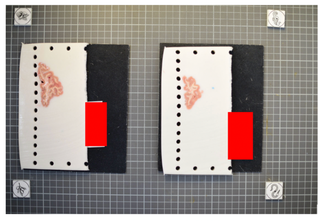
The fiducial form the four corners of our corrected image; hence all tissue should be within the rectangle created from the four fiducial corners. The following image shows slab photos where the fiducials were not placed sufficiently apart.

By drawing a rectangle with all fiducial markers, it is clear that much of the tissue lies outside of the pixel-corrected region.

In summary, here is an example of what an optimal photographic setup would look like, including the uniform, high-contrast background and provided fiducials located at known distances, and consistent lighting on all slabs.

Tip: It does not matter if slabs are not presented on a grid, as long as the distance between the fiducials is known. The software will draw digital rulers for your images later pixel-correction.
Recommended Directory Structure
We recommend the following directory structure for data and case organization. Each case should have its own directory, and within each case directory, create the following seven subdirectories to store the respective outputs:
- photos – Brain slab images (.JPG, .PNG).
- deformed - Pixel-corrected images.
- point_clouds – Files from the project collected from the surface scanner.
- mesh – Watertight mesh processed from point clouds on the scanner (.stl).
- masked – Binarized masks created from pixel-corrected photos.
- connected_components - .npz files showing the connected components for each image.
- recon - Final reconstructed volumes, and segmentations.
Note that during the image preprocessing GUI files under deformed, masked, and connected_components will be automatically generated. After each step, ensure that your data is saved to the appropriate subdirectory. Below is an example of how files should be organized in the recommended structure:
|
|


Photo Preprocessing
The following guide will walk through the steps to preprocessing the brain slab images. This includes pixel correction, binarizing images, and selecting connected components. Make sure Freesurfer is properly sourced, and you have downloaded the model weights before continuing with the tutorial.
Pixel Correction Using Fiducials
Using the provided fiducial markers, we can correct for non-uniformities in pixel size across the images. If not available this step can be skipped retrospective correction modes can be used in the dissection_photo_gui covered in the next section. For images with fiducials, a calibration is required for pixel correction. For best results, use an image of the setup without tissue.
To start the fiducial calibration use command fiducials_calibration

After loading the image, start the calibration process.

Pan and zoom can be used to have a precise selection in these GUIs. First, select the center of one of the fiducials, followed by selecting the outer ring.
|
|
The first selection at the fiducial center. |
The second selection at the outer circle of the fiducial. |
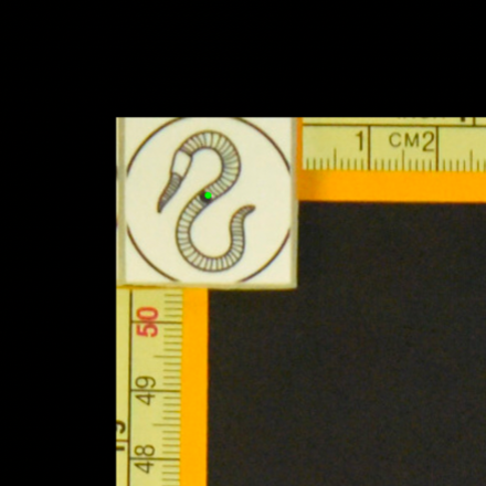
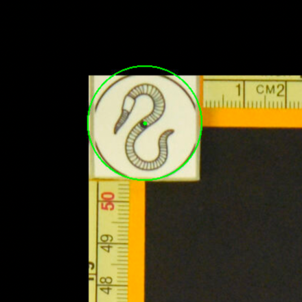
After selecting all the points, set the width and height between the fiducial markers. Next, click “Perform calibration,” to save a calibration '.npz' file. This calibration file will be used for automating pixel correction in subsequent steps, as long as the fiducial markers are not moved.
Dissection Photo GUI
The dissection photo GUI performs all preprocessing tasks, including pixel correction, binarizing images, and selecting connected components. To run the GUI, source Freesurfer and use command dissection_photo_gui. The first time the GUI is run it will display instructions on setup of model weights for the segmentation step.
Pixel Correction
In the first menu of the dissection_photo_gui select the input directory with the unprocessed gross photographs. Photographs should be set in the order such that tissue slabs are seen in the order they were cut. Additionally select the output directory where the pixel-corrected images will be saved. Here we have the option to load an optimal calibration file if available to automate pixel correction. Select Go! when you have defined the required directories.

If a calibration file was used the next widow will display the pixel-corrected images for quality assurance purposes. Click Next to proceed assuring the images were corrected.
If no calibration file is provided the next window will be for the Retrospective Correction mode. Select the type of calibration, 2-point, 3-point, or 4-point, and its relevant dimensions in millimeters. The 2-point calibration is used when there is a single axis of ground truth measurement, which enables rough pixel size correction (e.g., one ruler in the image). The 3-point calibration is used when there are three points on the corners of a rectangle – but the fourth point is not available (e.g., there are two orthogonal rulers). The 4-point version should be chosen if the four corners of a rectangle can be identified; this is the default model when the automatic mode with calibration file is used. The 3- and 4-point versions enable perspective correction (approximate with 3 points; exact with 4). We can pan and zoom to make precise selections on the image.
|
|
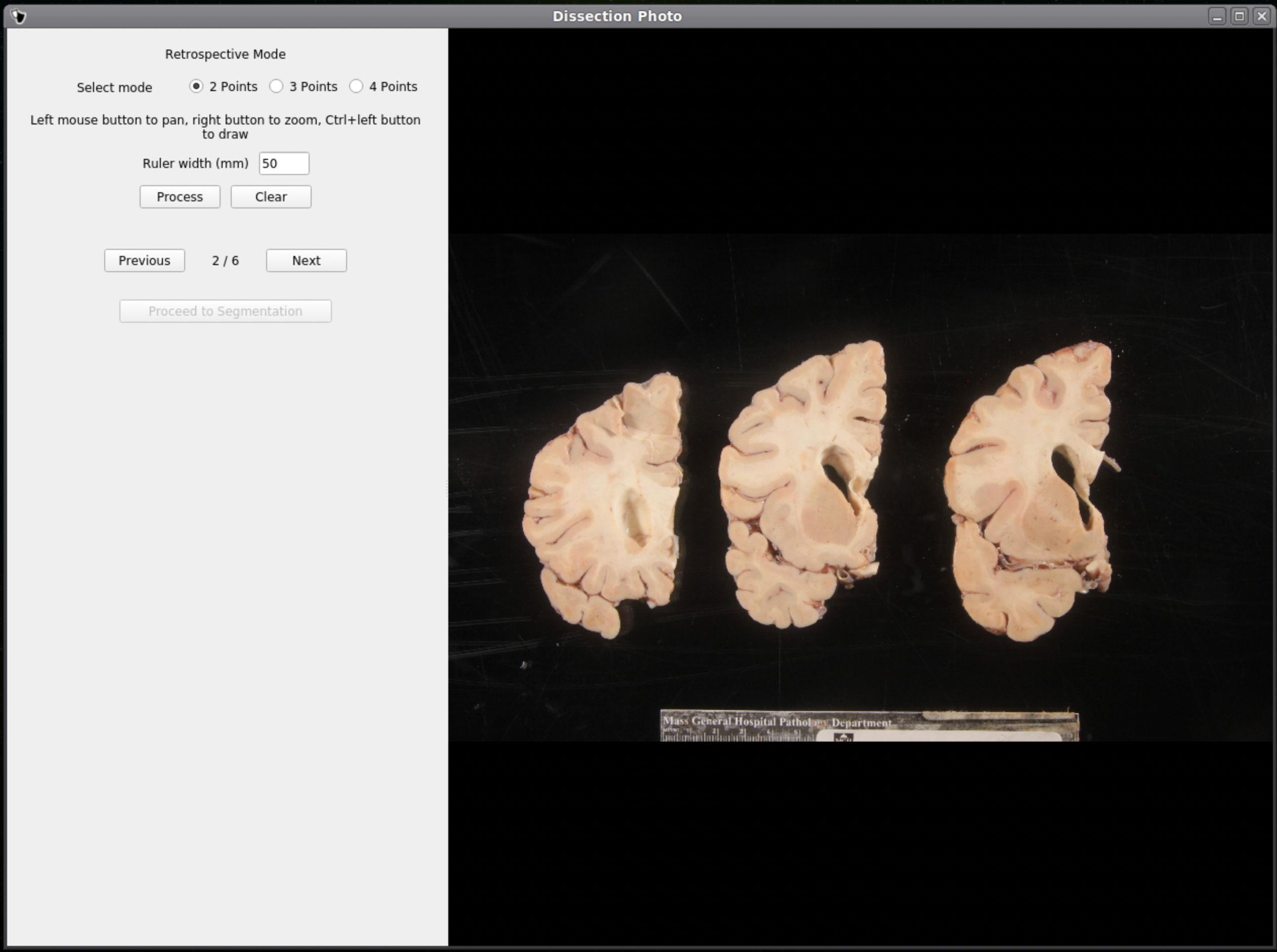

After pixel correcting all images, click Proceed to Segmentation to continue to the next step.
Tissue Segmentation
After selecting an output directory for the masked images, our automatic segmentation tool will immediately start predicting a binary mask per each photograph. If a GPU is available all five folds of the model will be run which will slightly increase segmentation accuracy. After the first photograph is segmented by the model, the user can start cleaning the predicted binary masks. Here the user can pan and zoom like before, but can additionally use a brush tool to remove or add any pixels. Remove any non-slice tissue and the background. The opacity of the predicted mask can also be changed using the provided slider, or toggled using Ctrl+Z.
|
|
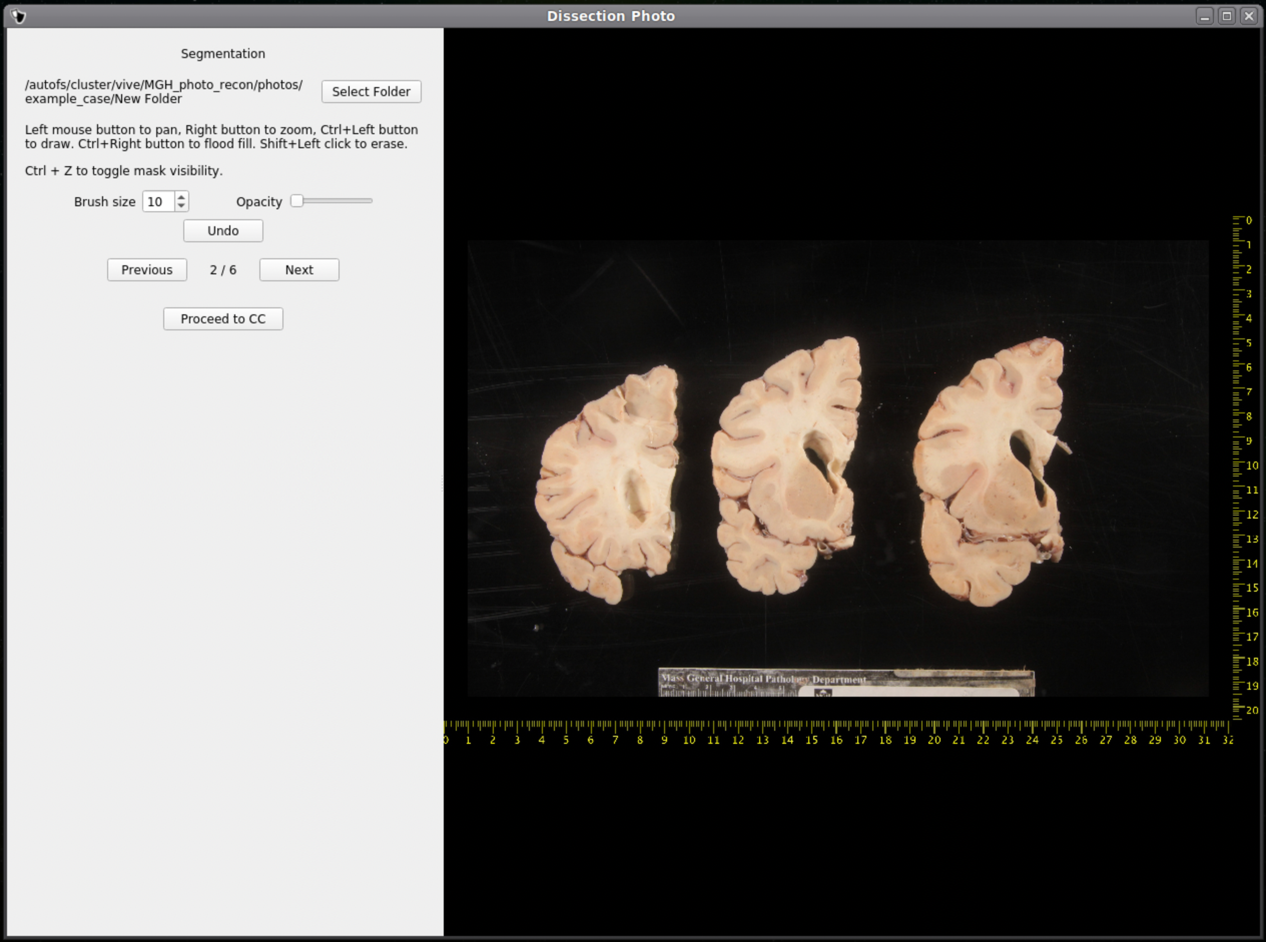

IMPORTANT: The cortical surface should not be part of the masks, so the first (if photographed from the anterior side) or last slice (if photographed from the posterior side) should NOT be considered. You can either leave it out of the mask or ignore it when processing with the GUI.
Once we are satisfied with the mask, click Next to proceed to the next image. After all images have been segmented and cleaned, click Proceed to CC to continue to the connected components step.
Connected Components
Like previous steps, select an output directory for the connected components masks. The connected components section of the GUI will display the masked and pixel-corrected photographs. Here the user will draw boxes around the tissue slabs in each photograph. The GUI will then save the connected components as .npy files.

For each image select slices in order, either anterior-posterior or posterior-anterior. Remain consistent of slice order on all photographs. Connected components are selected by clicking and dragging to draw a box in a region of each individual slab in the photograph. After a box has been drawn in each individual slab, click Next to save the output .npy file and move to the next image.
Tip: Make sure no boxes are overlapping.
Once a box is drawn over the tissue, the slab will be colored to show what is being included as one slice.

Above is an example of how to correctly draw the boxes within the brain slabs themselves. These boxes inform the GUI that the pixels connected to these slabs are all part of the same tissue slice. Note the box covers tissue from the temporal lobe as it can sometimes be disjoint from the rest of the slab.
Below is an example of how NOT to draw boxes for this GUI. Notice the occurrence of overlap between boxes and the inclusion of an abundance of black space. Try to keep the boxes drawn to small regions within the brain slabs themselves as to not include any background pixels.

Photo Reconstruction
Please see our separate page on the command mri_3d_photo_recon
Photo-Synthseg Segmentation
The 3D reconstructed stacks can be segmented with SynthSeg using the flag --photo. Please see the wiki page for SynthSeg for further information.
|
|
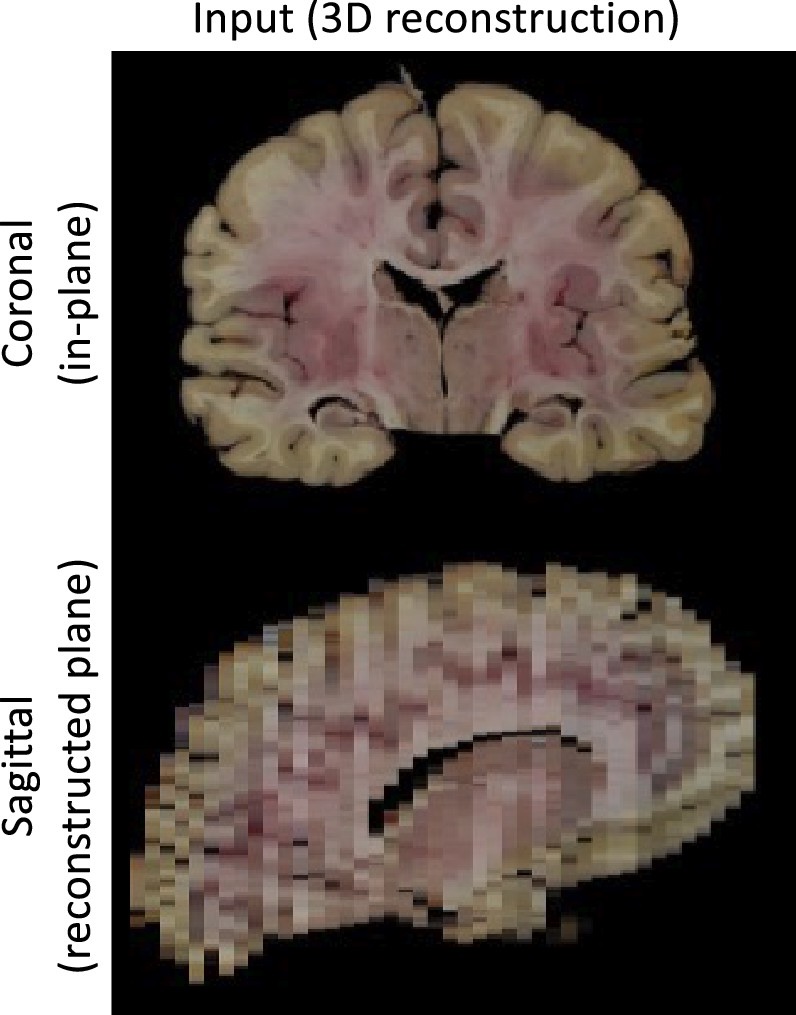

Example for running SynthSeg on a Left Hemisphere
- mri_synthseg \
- --i ./recon/photo_recon.mgz \
- --o ./recon/photo_recon_synthseg.mgz \
- --photo left \
- --parc