| Deletions are marked like this. | Additions are marked like this. |
| Line 1: | Line 1: |
|
= THIS PAGE HAS BEEN MOVED TO SHAREPOINT! = Please refer to this site/make edits here for the most updated information: https://partnershealthcare.sharepoint.com/sites/LCN/SitePages/Fixing-Geometric-Inaccuracies.aspx ---- <<BR>> <<BR>> <<BR>> |
To follow this exercise exactly be sure you've downloaded the tutorial data set before you begin. If you choose not to download the data set you can follow these instructions on your own data, but you will have to substitute your own specific paths and subject names.
Fixing Common Geometric Inaccuracies in White Matter Surfaces
Before you begin editing inaccuracies, you will want to set your SUBJECTS_DIR environment variable to the correct path. To do this, change to the tutorial directory, and then set the SUBJECTS_DIR variable to this current working directory:
cd $TUTORIAL_DATA/buckner_data/tutorial_subjs
setenv SUBJECTS_DIR ${PWD}
Manual Editing
First, open 008_manual_edits_before in tkmedit with the white matter volume (main) and brain volume (aux) simultaneously, and the lh white surface loaded on top:
tkmedit 008_manual_edits_before wm.mgz lh.white -aux brain.mgz
You can use Ctrl-1 and Ctrl-2 to switch back and forth between the main and aux volumes.
Geometric inaccuracy due to brain lesion
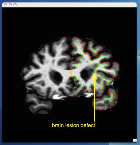
With the brain volume displayed and the surfaces overlayed in tkmedit scroll through to verify that the surfaces follow the actual surface of the cortex. You will notice an area as you get to the anterior horn of the lateral ventricle (around slice 155) where both the white surface (yellow line) and pial surface (red line) do not follow the surface of the brain, but in fact cut into it. This geometric inaccuracy is caused by an area near the lateral ventricle where white matter has been marked as non-white matter, and needs to be filled in the 3D volume. In this case, the autofill routine has already filled the ventricles, but the brain pathology resulted in an incorrect segmentation.
By switching the view back to the wm volume, you can see that this area has been left out of the wm volume completely.
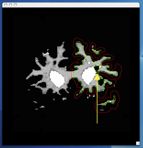
Use the arrow keys to scroll through the individual slices in the volume, until you get a good idea of where the problem starts and ends. Start filling in voxels when the inaccuracy appears, and keep filling them in slice by slice until the problem is no longer visible. The coronal view and a brush radius of one or two are good settings for painting in voxels. Zoom In and Out either by using the icons in the tkmedit Tool window or by Ctrl-right mouse button (Zoom In) and Ctrl-left mouse button (Zoom Out) to help you see the inaccuracy.
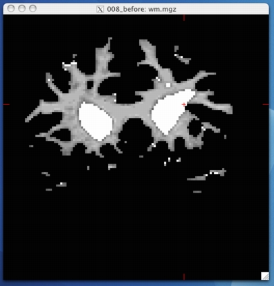
To begin editing voxels, click on the Edit Voxels Tool button, then go to Tools -> Configure Brush Info... Set the radius to be 2, and Shape to be Circle. Use the middle button on your mouse to begin painting in the voxels. If you fill in too many voxels, the right mouse button acts as an eraser. Start with slice 155, when you are done filling the region, your slice should look like this:
Go to the next slice, and fill in this slice in the same way. You will notice that the hole is not completely enclosed. To see where the boundary should be, switch back and forth between the brain and wm volume with Ctrl-1 and Ctrl-2. Use the brain volume as a guide, and make the boundary of the voxels that you paint in correspond as closely as possible to the boundaries suggested in the brain volume.
You will need to continue filling in slices in this fashion until the region is completely filled in. Open a second tkmedit with the 008_manual_edits_after wm volume, and for each slice check your results with the corresponding slice in the 008_manual_edits_after volume. The 008_manual_edits_after volume has the region filled in both the right and left hemispheres. At any time, you can save the changes youve made to the wm volume by selecting Save Volume in tkmedits File menu, and clicking OK. You can verify your results by viewing the changes made to the 008_manual_edits_after wm volume
Tips:
- Sometimes regions may appear enclosed in some slices (i.e. appear as holes), open in subsequent slices (i.e. no longer appear as holes), then enclosed again as you scroll forward. The rule of thumb when editing these is to keep filling until you reach the slice where they finally open up and are no longer enclosed.
When filling in regions that are in both hemispheres, you may opt to fill them in both hemispheres at the same time, when you become more comfortable with editing inaccuracies. To load the white surface for the other hemisphere you will need to go to File --> Aux Surface --> Load Aux Main Surface and select the other hemisphere's white surface (i.e., rh.white). This will load the rh.white surface as the Aux surface and you can now follow the surfaces for both hemispheres at the same time. All available surfaces can be displayed by selecting them in tkmedits Display menu.
- When editing geometric inaccuracies in the future, you may find it easier to edit the first slice and last slice first, thereby capping the slices that need filling. Then you just need to fill all the slices between the endcaps.
- Sometimes there is variation between a subjects left and right hemispheres, so that in a particular slice one hemispheres region will finally open up, but the other hemispheres region is still enclosed. In such cases, continue to fill the enclosed region only, even though the other is open. This will address the topological problem.
Surface shown after the inaccuracy is corrected:
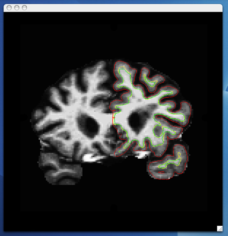
This image shows how your edits affect the inflated surface. It is used for illustrative purposes only; to save time, you may prefer to edit all visible inaccuracies before recreating the surfaces.
After you have saved all of your edits, you can recreate the final surfaces with:
recon-all -autorecon2-wm -subjid 008_manual_edits_before
Temporal Lobe
After initial segmentation, some subjects may have an additional geometrical inaccuracy in the temporal lobe, resulting in the disconnection of thin gyri. This results from the weak intensity obtained from the thin strands of temporal gyri and it is addressed by thickening the strand(s).
Open 111_manual_edits_before in tkmedit with the white matter volume (main) and brain volume (aux) simultaneously, and the lh white surface loaded on top:
tkmedit 111_manual_edits_before wm.mgz lh.white aux brain.mgz
As you scroll through the slices and look at the temporal gyri as you move further forward. You will find that one gyrus detaches and then reattaches a few slice later. The problem is visible in slices 133-135
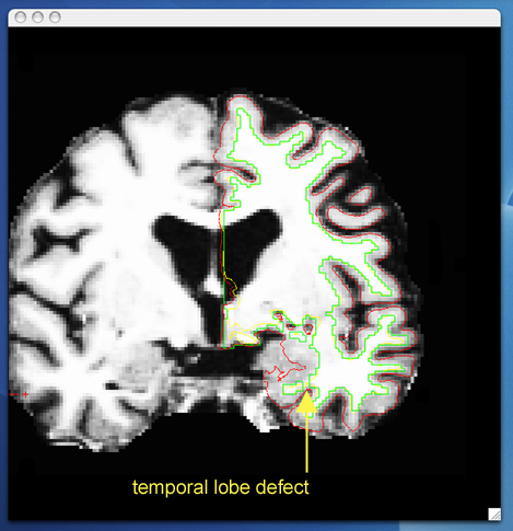
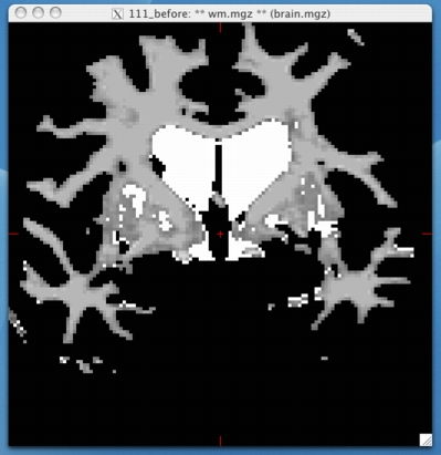
This gyrus will need to be reconnected to fix the inaccuracy. As in the brain lesion manual edit, paint in voxels to reconnect the islands to the main parts of the gyri, using the brain.mgz volume as a guide. When you are finished, your slice should look something like this
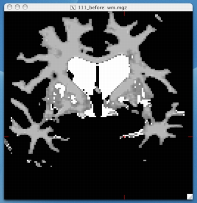
Continue with the rest of the slices where the inaccuracy is present. When reattaching islands of white matter, keep in mind that the voxels are not considered connected if they only touch at the corners. They must share an entire edge in order to be connected. When you are finished with your manual edits, make sure to save your changes to the volume by selecting Save Volume in tkmedits File menu, and clicking OK.
Frontal Lobe: non-white matter classified as white matter
Sometimes non-white matter (i.e., skull) is included as white matter. To view this keep 111_manual_edits_before loaded in tkmedit as before. Scroll through the brain volume slices, with the lh.white surface shown, and as you get towards the frontal lobe you will see a group of voxels included as white matter, they are surrounded by the white surface (yellow line). This group lies outside of the pial surface (red line) and is clearly not white matter. In order to correct this inaccuracy, it is necessary to delete the voxels which are not part of the white matter.
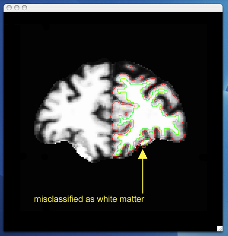
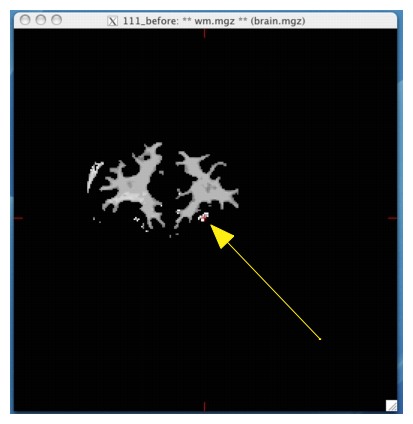
Using Ctrl-1 and Ctrl-2 to switch back and forth between the brain and wm volumes, you can clearly see that this region should not be labeled as white matter. To delete these voxels, click the Edit Voxels Tool button in the tkmedit toolbar, and put your mouse cursor over the voxels you want to delete. Delete them with the right mouse button. This is what slice 179 should look like after you have deleted the errant voxels:
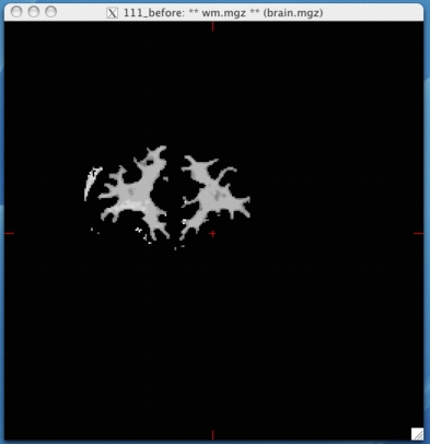
Go through the slices with the up and down arrows, continuing to delete voxels until the inaccuracy is no longer there. (It spans approximately 30 slices.) You can check your results by looking at the 111_manual_edits_after wm.mgz volume in tkmedit. Note that in this volume, only a few of the voxels have been removed from each slice, instead of removing the entire inaccuracy. This is because you only need to remove as many voxels as is necessary for the segmentation to classify this region as non-white matter. Until you are more comfortable with editing inaccuracies, go ahead and remove all of the voxels. More practice will give you a better feel for how many voxels need to be removed.
Frontal lobe: white matter classified as non-white matter
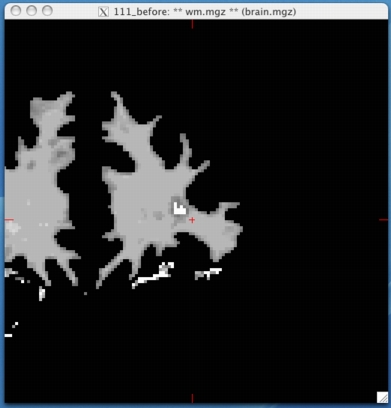
Sometimes white matter can be mistakenly excluded from the wm volume and subsequent surfaces. Continue looking at 111_manual_edits_before loaded in tkmedit as above, with the lh.white surface loaded on top. Scrolling through the slices further forward in the volume you will see that the white surface (yellow line) begins to cut into the white matter of the brain.
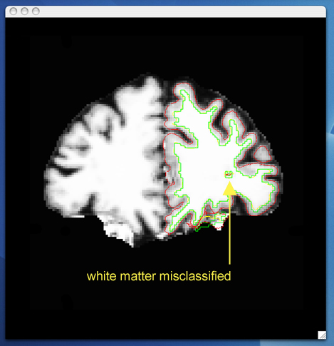
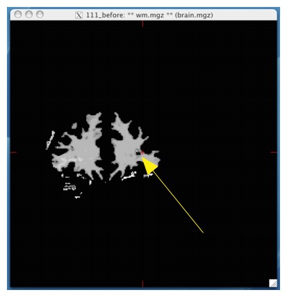
Use Ctrl-1 and Ctrl-2 to toggle between the wm and brain volume to be sure that the hole should indeed be labeled white matter. Use the same method used to fill in this hole as described earlier. When you are finished, slice 170 should look like this:
Scroll through the slices and fill each hole until the inaccuracy disappears. When you are done, you can check your results by opening up the 111_manual_edits_after wm.mgz volume in tkmedit.
Lateral Ventricle
The automatic edits made to to wm volume will fill the lateral ventricles. On occasion they are not filled entirely. Continue looking at 111_manual_edits_before in tkmedit, with the lh.white surface loaded on top. As you scroll to the posterior portions of the brain you will see the white surface (yellow line) start to follow the edge of the ventricle.
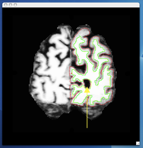
When you toggle between wm and the brain volume, you can see that this portion of the ventricle should be filled in. This inaccuracy can be corrected in the same fashion as the inaccuracies above, using the Edit Voxels tool to fill in the missing voxels.
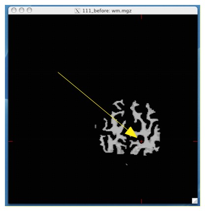
When you are finished filling in slice 53, it should look like this:
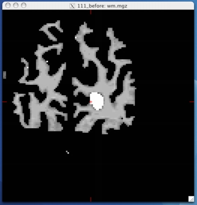
Continue filling in this region until the hole disappears. The geometric inaccuracy is present from slices 50 through 168.
The remaining inaccuracies are other examples of commonly seen problems with brain topology. You may choose to correct these on your own, using the 111_manual_edits_after volume as a guide for what your finished result should look like.
Optic Nerve
The optic nerve appears as a sharp projection on the inflated surface, and although it doesn't result in a geometric inaccuracy, it should be removed. The high curvature of this non-cortical structure unnecessarily complicates flattening and spherical morphing. Find the first sagittal slice where the optic nerve is present, and erase it. Continue to do the same when scrolling through each subsequent slice until the optic nerve is no longer visible. A brush size of 1-2 works well for this edit. Comparing the T1 image is useful in slices where the optic nerve looks fragmented. When finished, be sure to repeat the process in the other hemisphere.
