Inspection of Freesurfer Output
In this exercise you will visualize and inspect correctly processed output data so that you can become familiar with what the end product should look like. The exercise will take you through a variety of output, but is not necessarily the recommended procedure to take when trying to verify each subject for a real study. Some outputs are only necessary to check when troubleshooting, for example. However, it is a good idea for new users to become familiar with the variety of outputs and how to view them.
Preparations
If You're at an Organized Course
If you are taking one of the formally organized courses, everything has been set up for you on the provided laptop. The only thing you will need to do is run the following commands in every new terminal window (aka shell) you open throughout this tutorial. Copy and paste the commands below to get started:
setenv SUBJECTS_DIR $TUTORIAL_DATA/buckner_data/tutorial_subjs
cd $SUBJECTS_DIR
To copy: Highlight the command in the box above, right click and select copy (or use keyboard shortcut Ctrl+c), then use the middle button of your mouse to click inside the terminal window (this will paste the command). Press enter to run the command. These two commands set the SUBJECTS_DIR variable to the directory where the data is stored and then navigates into this directory. You can now skip ahead to the tutorial (below the gray line).
If You're not at an Organized Course
If you are NOT taking one of the formally organized courses, then to follow this exercise exactly be sure you've downloaded the tutorial data set before you begin. If you choose not to download the data set you can follow these instructions on your own data, but you will have to substitute your own data paths and subject names. These are the commands that you need to run before getting started:
tcsh
source your_freesurfer_dir/SetUpFreeSurfer.csh
setenv SUBJECTS_DIR $TUTORIAL_DATA/buckner_data/tutorial_subjs
cd $SUBJECTS_DIR
Notice the command to open tcsh. If you are already running the tcsh command shell, then the 'tcsh' command is not necessary. If you are not using the tutorial data you should set your SUBJECTS_DIR to the directory in which the recon(s) of the subject(s) you will use for this tutorial are located.
Viewing Volumes with Freeview
With one Freeview command line, you can load several output volumes, such as brainmask.mgz and wm.mgz; the surfaces, rh.white and lh.white; and the subcortical segmentation, aseg.mgz. Copy and paste the command below inside the terminal window and press enter:
freeview -v \
good_output/mri/T1.mgz \
good_output/mri/wm.mgz \
good_output/mri/brainmask.mgz \
good_output/mri/aseg.mgz:colormap=lut:opacity=0.2 \
-f good_output/surf/lh.white:edgecolor=blue \
good_output/surf/lh.pial:edgecolor=red \
good_output/surf/rh.white:edgecolor=blue \
good_output/surf/rh.pial:edgecolor=red
Some notes on the above command line:
- good_output is the name of the subject
- The flag -v is used to open volumes
- brainmask.mgz : skull-stripped volume primarily used for troubleshooting
- wm.mgz : white matter mask also used for troubleshooting
- aseg.mgz : subcortical segmentation loaded with its corresponding color table and at a low opacity
- The flag -f is used to load surfaces
white & pial surfaces are loaded for each hemisphere & with color indicated by 'edgecolor'
After hitting enter, a freeview window should open showing you the outputs you specified:

The menu on the left shows which files have been loaded.
Use the  buttons at the top to change which orthogonal view appears in the main viewing window. Let's go with coronal for now. You can also use the
  buttons to change the organization of the viewing panes. To change which brain slice you are viewing, use the 'Page Up' or 'Page Down' keys on your keyboard. (Mac users: press the fn key while using the up and down arrows.)
While Freeview can load many volumes at once, you cannot necessarily see them all at once. You are able to see whichever volume is at the top of the list in the menu on the left. An exception to this are volumes such as the wm.mgz and aseg.mz which can be made translucent, allowing you to view the information they contain simultaneously with the volume directly below it on the list. For example, you are currently seeing information from both the aseg (labeled structures) and the brainmask (voxel intensities).
You can hide or turn off a layer by unchecking the check box next to the layer name. Try this out - uncheck the box next to 'aseg'. Now you can see just the brainmask. You can also use the up and down arrows (located below the menu on the left) to move the aseg down on the list, below the brainmask (try it!). Let's now move the wm volume to the top of the list but instead of using the arrows, try this shortcut: double click on where it says 'wm'. It should automatically move to the top. The menu should now look like this:

and the viewing window should look like this:

Keyboard Shortcut: Alt-c will allow you to quickly cycle through all the layers. Every time you hit it, the volume at the top of the list will move to the bottom of the list.
When the Navigation button  is chosen, you can move the image in the viewing window around by holding down the middle mouse button and dragging the mouse where you want the image to go. Try it out. You can also move the image more slowly using the up/down and left/right keys. To zoom, scroll with the middle mouse button. In this navigation mode, notice the cursor (little red crosshair) moves to wherever you left click. When you change the orientation (to axial or sagittal), you will be viewing the slice that intersects with the cursor's location. To illustrate this point, if you are in the viewing pane selected here:
You'll notice all the planes will shift based on where you move the cursor.
One other important thing to note is that any action you do in the viewing window (i.e. erasing, changing brightness, etc.) will take place on whichever volume is currently highlighted in the left menu, regardless of which file is at the top of the list.
Now that you know the basics, you can make your way through the data. To verify that FreeSurfer did a good job, you will want to check:
- Whether the surfaces accurately follow the gray matter and white matter boundaries.
- Whether the aseg accurately follows the subcortical intensity boundaries.
Checking the Surfaces
Double click on 'brainmask' in the left menu to bring it to the top of the volume list. The white surface (blue line) is used to calculate total white matter volume and should accurately follow the boundary between white matter and gray matter. The pial surface is used to calculate cortical gray matter volume and should accurately follow the boundary between the gray matter and the CSF.
As you scroll through the slices checking the surfaces for accuracy, keep in mind that you are looking at a 2-dimensional rendering of a 3-dimensional image - be sure to look at more than just one view (i.e., sagittal, coronal and horizontal). You can turn the surfaces off and on by checking and unchecking them in the left menu under where it says 'Surfaces'. As you do this, ask yourself: would you draw the boundary in the same location?
Keyboard Shortcut: Alt-f will turn on and off whichever surface is highlighted in the menu window.
To help verify accuracy, adjust the brightness and contrast so you can easily identify the shift in intensity between gray and white matter. To do this, left click on the image while holding down the 'Shift' key and drag your mouse. (Make sure the brainmask volume is highlighted in the left menu in order for this to work.) The other way to do this is via the 'Window' and 'Level' sliders underneath the left menu.
There are regions where the surfaces are not intended to be accurate that you should be aware of:
- Areas around the hippocampus and amygdala. The surfaces will not completely include or exclude certain subcortical regions. These inaccuracies can be ignored as subcortical regions are excluded from the cortical measures and subcortical volume is measured by the aseg, not the surfaces.
- For an example of this, scroll to coronal slice 137 (slice numbers appear in the upper right hand corner of the viewing window).
- Along the midline cut, it is possible to see some overlapping of the surfaces from one hemisphere to another. The medial wall is not included in the cortical measures so this can generally be ignored.
Subcortical Segmentation
Double click on the aseg so it is directly above the brainmask in the left menu. <BR>> 
This will show the complete segmentation of the subcortical structures. Each structure is labeled with a unique color/number distinction. If you click on a voxel the structure's name and number label will be shown in the 'Cursor' section under the viewing window next to the word, 'aseg'. If you hover over a voxel where the cursor is not located, the value of that voxel will appear under the 'Mouse' section.
Keyboard Shortcut: Alt-v will turn on and off the layer that is currently highlighted.
Make sure 'aseg' is highlighted in the left menu and press Alt-v to turn it off and on. While doing this, make sure the aseg is accurately following the underlying intensity boundaries of each structure. You can also adjust the 'Opacity' slider to better see the underlying brainmask.
Keyboard Shortcut: Alt-a and Alt-s will change the opacity of the layer that is currently highlighted.
Other Things To Do in Freeview
Below, we introduce you to other volumes and techniques which are good to be familiar with, especially when troubleshooting.
Aparc+Aseg segmentation
First, close the aseg volume by highlighting it and the clicking this button  . Then, to load the aparc+aseg segmentation go to File > Load Volume, click on the yellow folder icon, and browse to the aparc+aseg.mgz. Once you have selected the file, click 'Open', and then 'Ok'. When it loads, 'Grayscale' will be selected as the Colormap. This will obscure the brainmask beneath. In the Color map section on the left, choose 'Lookup Table'. Then adjust the opacity so that you can see the brainmask and aparc+aseg at the same time. When loaded, it will look like this:
 ![]()
This volume shows the parcellated cortical ribbon at the same time as the segmented subcortical structures (later we will look at the cortical labels on the surface). Click around the cortex to see the name of each cortical region under the 'Cursor' section. The aparc+aseg.mgz uses the Desikan-Killiany atlas. To see the Destrieux atlas, you would load the aparc.a2009s+aseg.mgz
Skull Strip
Close the aparc+aseg. As you scroll through the brainmask volume, notice that there is no skull left in your image. You should also not see any regions of cortex or cerebellum missing from this volume. Bring the T1.mgz to the top of the volume list and toggle between it and the brainmask.mgz volume (Alt-v) to verify that the skullstrip has worked properly. In the TroubleshootingData tutorial, we'll go over what to do if there was a skull strip error.
Intensity Normalization
Scroll through the brainmask volume and notice that the intensity is all uniform. You should not see any very bright or very dark spots in the white matter or gray matter. If you click on a voxel in the white matter, you can see that it has been normalized to an intensity of (or very close to) 110 (look under the Cursor section next to where it says 'brainmask'). When wm voxels are far from a value of 110, they may be erroneously excluded from the white surface. In the TroubleshootingData tutorial, we'll go over what to do if there was an intensity normalization error.
WM Volume
Double click on the wm volume to bring it to the top of the list. This volume is FreeSurfer's initial segmentation of the white matter (shown in gray) with additions from the automatic topology fixer (in white). This "mask" is the starting point for the white surface which grows out from here and stops at a more accurate location using the intensity gradients in the brainmask.mgz volume as a guide. The wm.mgz can be used to add missing wm voxels or delete voxels that are not white matter but were included in the surface. In the TroubleshootingData tutorial, we'll go over how to do this and when. For now, it will be good to learn how to change the wm mask to a heat overlay for ease of editing. With wm highlighted in the left menu, take a look at the options next to Color Map and choose 'Heat' or 'Jet'. Then adjust the opacity so you can also see the brainmask underneath (down to around .25). It should look like this:

This could have also be done via commandline when first loading the wm in Freeview if we used this command: freeview -v wm.mgz:colormap=heat:opacity=0.25 brainmask.mgz (Note: You don't need to run this command.)
You can now close Freeview by hitting the X on the display window or Ctrl-q.
Viewing Surfaces in 3D using Freeview
We're now going to view several surface overlays. You could view the volumes discussed above and the overlays discussed below all in one Freeview session. They are separated in this tutorial only for simplicity. The examples below are displayed only on the left hemisphere, however, you could view both hemispheres at the same time. Here are the things you can look at with freeview:
- pial, white and inflated surface
- sulcal and curvature maps
- thickness maps
- cortical parcellation
By default, Freeview will display curvature information on any surface loaded. In several examples below, you will be asked to turn off the curvature after loading a surface in order to view other information.
freeview -f  good_output/surf/lh.pial:annot=aparc.annot:name=pial_aparc:visible=0 \
good_output/surf/lh.inflated:overlay=lh.thickness:overlay_threshold=0.1,3::name=inflated_thickness:visible=0 \
good_output/surf/lh.inflated:overlay=lh.curv:overlay_threshold=0.08,0.4:name=inflated_curv:visible=0 \
good_output/surf/lh.white:visible=0 \
good_output/surf/lh.pial:visible=0 \
good_output/surf/lh.inflated
Some notes on the above command line:
lh.pial:annot=aparc.annot loads the Desikan-Killiany cortical parcellation on the pial surface
:name=pial_aparc:visible=0 changes which name shows up in the menu display and turns off this layer
lh.inflated:overlay=lh.thickness:overlay_threshold=0.1,3 loads the thickness overlay on top of the inflated surface and sets the min and max thresholds to display
Once the surface is loaded, you will see the green and red blobs on the surface which correspond to curvature. We will turn them off for now. Do this by selecting Off in the Curvature drop-down menu. To get rid of the yellow lines being displayed on the surface (corresponding to the 3 slice views), right-click on the surface and uncheck Show Slices (3D View), or hit Crtl+Shift+S.
inflated left hemisphere

Alt+C
pial left hemisphere
Again, you will see the green/red blobs on the surface which correspond to curvature. We will turn them off for now. Do this by selecting Off in the Curvature drop-down menu.

Alt+C
white left hemisphere
Again, you will see the green/red blobs on the surface which correspond to curvature. We will turn them off for now. Do this by selecting Off in the Curvature drop-down menu.

Alt+C
curvature on inflated left hemisphere
Again, you will see the green/red blobs on the surface which correspond to curvature. We will turn them off for now. Do this by selecting Off in the Curvature drop-down menu.

Alt+C
thickness on inflated left hemisphere

Alt+C
aparc on inflated left hemisphere

END
TKSURF text below
You should see a Tksurfer window open up to this:

You are currently looking at the inflated surface. The surface can be rotated using the buttons in the navigation toolbar: ![]()
![]()
![]()
![]()
![]()
![]() . Use the redraw button
. Use the redraw button  to repaint the image if it gets corrupted by window movement.
Mouse Shortcut: Right click in the Tksurfer window to redraw.
Inflated surface The inflated surface is good to look at when checking to see if you need to make edits to the wm.mgz volume. You'll notice as you inspect this surface that it is smooth and free from holes, bumps and other defects. If you click on the surface, you will see the coordinates of the vertex you clicked on in the Tools window under "Cursor". To clear the marks made on the surface after clicking on it, you can go to Edit > Unmark All Vertices.
Keyboard Shortcut: You can unmark one vertex at a time by using Ctrl+Shift+middle click on each. Troubleshooting Tip: If at any point clicking in the Tksurfer window automatically causes you to zoom in, your Ctrl key is stuck. Trying hitting the Ctrl button a few times to get it unstuck.
Pial Surface All surfaces (pial, white, orig) have been loaded as a default along with the inflated surface. You can switch to the pial surface by clicking the  button. You should see this:

The pial surface is showing you the outer boundary between the gray matter and CSF (cerebrospinal fluid). This is the same file that was viewed in Tkmedit, just represented as a 3D surface image rather than the red outline on the 2D slices in the brainmask volume. You can inspect this surface by rotating it around as you wish. White Surface Click on the  button to view the white surface. This is what the white surface will look like:

The white surface shows the boundary between the white and the gray matter. Again, this is the same file that was viewed in freeview (as the yellow outline) just represented in a 3D manner. You can inspect this surface by rotating it around as you wish. Curv and Sulc Files Switch back to viewing the inflated surface of the brain by pushing the  button. You can now load in the curvature file, lh.curv, by holding Ctrl and right clicking on the
  button on the Tksurfer Tools window. The box that pops up will automatically have selected the lh.curv file, so click ok. The curvature file will look like this:

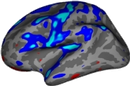
This is showing the slightly smoothed mean curvature. It has the units of 1/mm, and with an outward pointing normal vector field. Negative regions are folded-out and shown in green (gyral), and positive regions are folded-in and shown in red (sulcal) To view the sulc file you could have changed the dialog box to say lh.sulc when right clicking on the curv button as described above, or you can go to File > Curvature > Load Curvature and browse to the lh.sulc file (found in $TUTORIAL_DATA/buckner_data/tutorial_subjs/good_output/surf/). Be sure you select the curvature file for the correct hemisphere, if you select the wrong one it will not look right. The lh.sulc file will load a slightly different display of green/red values than the lh.curv. These are showing the sulcal depth and again here the red regions are sulcal and the green regions are gyral. You can still view this overlay as you switch to the pial or white surfaces using the and buttons. Thickness Maps To view the thickness maps it is probably best to toggle off the curvature . You can load the thickness map, lh.thickness, by holding Ctrl and right clicking  on the Tksurfer Tools window. Browse to the lh.thickness file (you may have to find the subject "good_output" from the list of subjects, then navigate to the surf directory and select lh.thickness). Be sure you select the thickness file for the correct hemisphere, if you select the wrong one it will not look right. The lh.thickness map should open up and look like this:

You can adjust the thresholds of the map by going to View > Configure > Overlay which will open a new window that will allow you to change the thresholds. First click the Thresholds: Linear checkbox. Then try some different settings and see how it affects the display on the map (try a Min of 1.0 and Max of 3.0, Min of 2 and Max of 5, etc). After you change the min and max values be sure to hit Apply to see the changes. If the Apply button is not visible to you, hit the space bar to Apply the changes. Cortical Parcellations To view the cortical parcellation it is probably best to toggle off the curvature and thickness files (if any are still visible), and to switch to the pial surface, . You can load the parcellation by going to File > Label > Import Annotation and browsing to the lh.aparc.annot file (found in $TUTORIAL_DATA/buckner_data/tutorial_subjs/good_output/label/). Be sure you select the label file for the correct hemisphere, if you select the wrong one it will not look right. The lh.aparc.annot should open up and like this:

Click on a color and view the name of the cortical region in the Tksurfer Tools box. Rotate the brain so you are looking at the medial wall. Notice that all subcortical gray matter is not a part of the surface labels (because again, those areas do not count towards the cortical surface measures). You can also switch to the inflated view and turn the labels to outlines using the  button. The parcellation that is loaded here was created with the Desikan-Killiany atlas. By default there are two parcellations that are made when recon-all is run. The second parcellation, called ?h.aparc.a2009s.annot, is created with the Destrieux atlas. The difference is the number and designation of the areas that are labeled. You can load this second parcellation by first going to File -> Label -> Delete all Labels. This will remove the first parcellation. Then you can repeat the steps for loading a parcellation, this time browsing to lh.aparc.a2009s.annot to load the second parcellation.
Using tksurfer and Freeview together
When you are viewing the same subject in Freeview and Tksurfer at the same time you can click on a point on the aseg in freeview (along the surface, not subcortical structures) and automatically locate the same point on the surface in tksurfer. To do this, first open a new terminal window so you can open up the same subject in Freeview as you have open in Tksurfer:
freeview good_output/mri/brainmask.mgz \
good_output/mri/aseg.mgz:colormap=lut:opacity=0.2 \
-f good_output/surf/lh.white:edgecolor=blue good_output/surf/lh.pial:edgecolor=red \
good_output/surf/rh.white:edgecolor=blue good_output/surf/rh.pial:edgecolor=red
Click on a point along the surface in the aseg in freeview (along the cortical ribbon, not on one of the subcortical structures. Next, go to File > Save point. This will save the cursor position. Then, in the Tksurfer Tools window, click the "goto saved point" button  . This will now bring you to the same point, only on the surface. Look for the new location of the cursor on the surface of the volume. When you are done, you can close Tksurfer by going to File > Quit. You can close Freeview by hitting the X on the display window or going to File > Quit . You can also do Ctrl-q to quit for both.
This tutorial was meant as an introduction to freeview and Tksurfer. For information on buttons or menu options not covered here, you can find out about them on the Freesurfer Tools wiki. top | previous | next